background image

5

II. Install Instrument

1. Environment Required

To ensure the best performance, the following conditions are required:

The best working temperature range is 16-35

and the humidity is 45-80%.

Keep it as far as possible away from the strong magnetic or electrical fields or any electrical

device that may generate high-frequency fields.

Set the unit up in an area that is free of dust, corrosive gases and strong vibrations.

Remove any obstructions or materials that could hinder the flow of air under and around the

instrument.

The power requirement is 220±22V@50±1Hz or 110±11V@60±1 Hz.

Use the appropriate power cord and plug into a grounded outlet.

If the local voltage is not stable enough, a manostat is required.

Be away from direct sunlight.

2. Voltage Confirmation

Be sure to set the instrument’s voltage switch at your local power supply, or severe damage

may occur!

3. Installation

Step 1: Check the packing list

Unpack the contents, check the materials with the Packing List. Any damage or

Lost found, please contact us or the local dealer.

Step 2: Position

Place the instrument on the stable table carefully.

Step 3: Install printer (Optional)

Make sure the printer is power off.link the printer’s data cable to the Instrument’s parallel port.

Step 4: Link the power cord

Make sure the instrument’s power switch is in the Off condition, link the power cord to the

instrument and insert another end in the socket provided with a protective earth contact.

Step 5: Switch on the power

Check again. Make sure that all the links are right. Switch on the power. Then the instrument begins

to self-test. After self-test and 15 minutes’ pre-warm, it can work. The self-test includes the following

steps:

Filter→Light Source Positioning→DarkCurrent→WLSelf-check→WEnergy→D Energy→ Room→

Battery Voltage(Fig.2-1)

After pre-warm, the instrument will ask the user to re-calibrate the system. (Fig. 2-2) Users can

decide if they need to re-calibrate the system or not.

Summary of Contents for BK-S360

Page 1: ...UV VIS SPECTROPHOTOMETER BK S360 User Manual BIOBASE GROUP Version 2020 11 ...

Page 2: ......

Page 3: ... 1 Environment Required 5 2 Voltage Confirmation 5 3 Installation 5 III Introduction of the Instrument 7 1 Introduction 7 2 Operation Panel 8 3 Keypad Description 8 IV Instrument Operation 10 1 Software System 10 2 Basic Operation 11 3 Before Measurement 12 4 Measurement 12 5 Tools 24 V Instrument Maintenance 26 1 Daily Maintain 26 2 Troubleshooting 26 3 Spare parts replacement 27 ...

Page 4: ...f Medical Treatment Part 1 2 About the Instrument Scanning Series UV Vis Spectrophotometer is an electrical test instruments which is widely used in the laboratories Use Frequency Intermittence Excessive Voltage Current No Pollution Class Class 1 3 Symbols Caution Danger Caution High Voltage Caution Hot Ground Fuse Recall this instrument will be called back by the appointed Electrical Treatment De...

Page 5: ...thickness The relation can be concluded as the following Formula which is called Lambert Beer Law T I Io A KCL log I Io A Absorbance C Concentration of the Solution K Absorbance Coefficient of the Solution L The length of the Solution in the light path I The intensity of the light focused on the A D after it permeate the solution to be measured Io The intensity of the light focused on the A D afte...

Page 6: ... and the test result can be stored in the RAM and printed out Multiple Wavelength Test the Abs and Trans of the same sample under different wavelengths can test the data from 8 wavelengths Kinetics Test the sample changes in a period get A t display the spectrum curve Spectrum Wavelength range 190 1100nm set up the range interval to test the max peak value curve of sample BIO Built in7 methods Cus...

Page 7: ... 3 Installation Step 1 Check the packing list Unpack the contents check the materials with the Packing List Any damage or Lost found please contact us or the local dealer Step 2 Position Place the instrument on the stable table carefully Step 3 Install printer Optional Make sure the printer is power off link the printer s data cable to the Instrument s parallel port Step 4 Link the power cord Make...

Page 8: ...6 Fig 2 1 Fig 2 2 ...

Page 9: ...Instrument 1 Introduction Appearance of the instrument Fig 3 1 Fig 3 1 1 Lid of the room 2 Operation Panel 3 Cell Holder 4 Rod 5 Fan 6 Fan Cover 7 Power Socket 8 Con Tem Port 9 Power Switch 10 USB 11 Print Port 12 USB Print Port ...

Page 10: ...3 2 1 LCD Displayer 2 Keypad 3 Keypad Description Input Parameters Wavelength and set 8 cell auto cell holder Delete the input value or stored data Cancel operation or return to former menu Calibrate 100 T 0Abs Load the files saved in the RAM Save the test results Start Cancel Test 1 2 ...

Page 11: ...9 Set Wavelength Print Test Result Confirm the input value or setting Scroll the menu or data Seek wavelength peak or set coordinate ...

Page 12: ...10 IV Instrument Operation 1 Software System Software System of Instrument Fig 4 1 Fig 4 1 ...

Page 13: ...cell holder In the setting menu to make corresponding cell position at the light path Then read the test data 5 Delete the Input Value When input value press to delete all the characters 6 Delete the test result and stored data Press to select in the test interface press to delete the test result or stored data Press to delete all data if nothing selected 7 Calibrate 100 T 0Abs Put the Reference i...

Page 14: ...ll the blocks in the light path and close the lid of the compartment Switch on the power supply to begin the self test 2 Pre warming After self test the instrument goes into pre warm state For accurate test at least 30 minutes of warm up is required 3 Check the Cuvettes The cuvettes must be clear and there s no remains of the samples on the surface of it Only Silicon Quartz cuvettes are permitted ...

Page 15: ...bs Step 5 Sample Measurement Put the sample to be measured in the light path the result will be displayed on the screen automatically Press to go into photometry data sheet Repeat Step 4 5 press to calculate the data into the data sheet test all samples Step 6 Save Open Print Data Press to save the result Press to choose store position press to input file name to confirm and save Save photometry p...

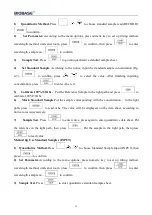
Page 16: ...concentration press to confirm After finished setting press to test successively or press to input standard sample Abs value P S Coefficient method without displaying curve Step 3 Set up Standard Curve Press to go into QTY Curveinterfaceto establish or select standard curve Fig 4 5 3 methods are under your choice Fig 4 5 Set up Standard Curve In the setup menu Method 1 Standard Sample read RECORD ...

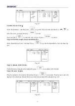
Page 17: ...h and press to calibrate 100 T 0Abs 6 Mark Standard Sample Put the sample corresponding with the concentration in the light path press to read Abs The value will be displayed on the data sheet according to notice to test successively 7 Sample Test Press to enter curve press again to enter quantitative data sheet Put the reference in the light path then press Put the sample in the light path then p...

Page 18: ...erence Sample in the light path and press to calibrate 100 T 0Abs 6 Test Sample Put the test sample in the light path press to read value Method 3 Coefficient method Input Regression Equation 1 Quantitative Method Press to select coefficient method PARAM toconfirm 2 Set Parameter According to the menu options press numeric key to set up fitting method wavelength method units and room press to conf...

Page 19: ...ample measurement interface In the Quantitative Curve interface Press to go into the Quantitative Test interface Fig 4 8 Fig 4 8 Step 5 Calibrate 100 T 0Abs Put the Reference Sample in the light path press to calibrate 100 T 0Abs Step 6 Measure Samples Place the sample to be tested in the light path press to measure Then the test result will display in the data sheet Repeat this step to finish mea...

Page 20: ...A2 A4 A4 3 Kinetics Step 1 Go into Kinetics Test Interface In the main menu press to select KINS Fig 4 12 Fig 4 12 Step 2 Setup Parameters Press function key to set up parameters input wavelength test time delay interval record range and room to confirm Press numeric key to choose test mode Abs or Trans Press numeric key to input test wavelength range 190nm 1100nm Press numeric key to input test t...

Page 21: ... 3 Calibrate 100 T 0Abs Put the Reference Sample in the light path press to calibrate 100 T 0Abs Step 4 Measure the sample Put the sample to be tested in the light path and press to begin the test Step5 Data Process After test press to enter data process interface Fig 4 13 Fig 4 13 Press to recover original data Press to change coordinate test time and range Press to enter data sheet display test ...

Page 22: ...0 Step 2 Setup Press to set up test mode press to choose Trans and Abs to confirm Press numeric key to set up no of wavelength can set up 8 wavelengths at most choose the wavelength no under your choice Press numeric key to set up wavelength then key to confirm After finished press to start testing Step 3 Calibrate 100 T 0Abs Press the sample in the light path according to notice press to calibrat...

Page 23: ...t data 5 Spectrum Step 1 Go into spectrum scan In the main menu press numeric key to choose SPEC Fig 4 15 Fig 4 15 Step 2 Set up scan parameters Function key to set up parameters according to notice set up Mode Source Light Interval Scan Range Record Range and Scan Speed to confirm after set up press to enter spectrum test interface Press numeric key mode Trans Abs Energy press key to choose test ...

Page 24: ...eet Press to confirm Press input record range Abs A value is 4 4 Trans T value is 0 200 Energy E value is 0 100 Press to confirm Press set scan speed Fast Middle Slow press to choose scan speed press to confirm After finishing settings press to enter spectrum test interface Step 3 Scan baseline Put the reference in the light path to scan baseline to cancel scan Step 4 Scan Sample Put the sample in...

Page 25: ...eak Value Press to print curve and data sheet Step 7 Save Data Press to choose store position press again to save input curve name and press to confirm Step 8 Open and Delete Curve Press to choose the curve you want and to open press to delete stored curve 6 BIO Step 1 Go into DNA Protein Test In the Main menu press to choose BIO Fig 4 17 Fig 4 17 Fig 4 18 Step 2 Choose Method Press numeric key to...

Page 26: ...test in the light path press to measure The result will display in the data sheet Fig 4 18 Step 6 Delete Data Press to delete the data Step 7 Store the Data After measurement press to store the result Input the file name by the numeric keypad press to confirm 5 Tools In the main menu press to select Tools Fig 4 19 Fig 4 19 1 W Lamp Press anduse to choose W Lampon or off and press to confirm Users ...

Page 27: ...tem begins to refresh Dark Current Note During the course opening the lid of the compartment is prohibited 4 Wavelength Calibration Press to re search D lamp energy curve 656 1nm The instrument will self calibrate when switch on Note During the course opening the lid of the compartment is prohibited 5 Languages Selection Press anduse to choose Languages and press to confirm 6 Clock Setup Press to ...

Page 28: ... the surface would cause measuring error 2 Troubleshooting 1 Dark Current Error when Self check Possible Cause Solution Open the lid of the compartment Close the lid of the compartment during the course of self test and switch on the power again 2 No Response After Power On Possible Cause Solution Bad contact in power supply Improve the contact Fuse melt Replace a new fuse 3 Printer Not Work Print...

Page 29: ...eplace the Fuse Danger Be sure to switch off the power and unplug the socket before replacement Step 1 Tools Preparation Prepare a 3 75 Flat Blade screwdriver Step Switch Off the Power Supply Switch off the power supply and unplug the socket Step 3 Take Out the Fuse Seat Take out the fuse seat by the screwdriver Fig 5 1 Fig 5 1 Step 4 Replace a New Fuse Pick out the spare fuse and replace it to th...

Page 30: ...amber after power off to avoid scald Step 1 Tools Preparation Prepare a 6 150mm Cross Blade screwdriver and a pair of glove Step 2 Power Off Switch off the power supply and unplug the socket Step 3 Open the Cover Unscrew the 4 screws indicated in Fig 5 3 Each side with 2 screws and remove the cover Fig 5 3 Step 4 Open the Cover of the Light Chamber Unscrew the 2 screws on the light chamber cover a...

Page 31: ...amp Fix the 2 screws and plug the connector again Fig 5 5 Step 6 Replace W Lamp Remember the direction of the filament before pull out the W lamp Be sure that the new lamp s filament is in the same direction as before Pull out the defected W lamp and draw on the cotton glove Insert the new W lamp as deep as possible on the lamp seat Be sure to keep the filament in the same direction as the old one...

Page 32: ... the entrance hole Fig 5 7 If the facula deviate to Left or Right then loosen the No 1 screws in Fig 5 8 and move the lamp seat to Left or Right until it focus on the center of the slot Then fix the screws If the facula deviate to Up and Down then loosen the No 2 screws in Fig 5 8 andmove the lamp seat Up and Down until the facula focus on the center of the slot Then fix the No 2 screws again Fig ...

Page 33: ...switch off the power supply and unplug the socket before open the Bottom Cover Step 1 Prepare the Tools Prepare a 6 150mm Cross Blade Screwdriver Step 2 Switch Off the Power Supply Switch off the power supply and unplug the socket Step 3 Open the Bottom Cover Plate Unscrew the 13 screws indicated in Fig 5 9 then remove the bottom plate Fig 5 9 Step 4 Replace the Battery Pick out the old battery an...

Page 34: ...32 Fig 5 10 Step 5 Finish Recover the bottom plate and fix the 13 screws then the course finishes ...

Page 35: ...33 Appendix 1 Consumable Sheet Deuterium Lamp Tungsten Lamp 10mm Cuvette Glass 4PCS BOX 10mm Cuvette Quartz 4PCS BOX ...

Page 36: ...inan City Shandong Province China Tel 86 531 81219803 01 Fax 86 531 81219804 Inquiry export biobase com Complaints customer_support biobase cc After sales service service_sd biobase cc service_ivd biobase cc Web www biobase cc www meihuatrade com www biobase com ...

Reviews: