


2
GENERAL NOTES
1.
GENERAL
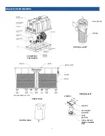
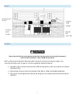
The treatment system is complete with all needed equipment as shown on the drawings and specified
herein. The following items of equipment are provided by BioMicrobics, Inc., with purchase of the
system: (a) the FAST system sub-assembly, (b) foot top and foot bottom, (c) blower assembly, and (d)
blower controls and alarms. All other items needed for installation and operation are not included.
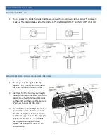
The contractor will install the FAST® treatment system as manufactured by BioMicrobics, Inc. The
contractor will ensure the proper fabrication of the tank, coordinate between the tank suppliers and
FAST® system suppliers, arrange delivery to the job site, and oversee the installation of the FAST® unit.
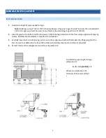
The tank must provide adequate pump-out access and must conform to local, state, and all other
applicable codes. The tank must also be level within ±1/2 in [12 mm].
2.
MEDIA
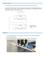
The FAST media is made of rigid PVC, polyethylene, or polypropylene, and it is supported by the
polyethylene insert. The media will be fixed in position and contain no moving or wearing parts, and it
will not corrode. The media has been designed (and will be installed) to ensure that sloughed solids
descend through the media to the bottom of the septic tank for easy cleanout.
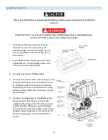
3.
REMOTE MOUNTED BLOWER
The blower must be set in a dry, stable place, and its elevation must be higher than the normal flood
level. A two-piece, rectangular housing is included with the unit. The discharge air line from the blower
to the FAST system is not included and must be provided and installed by the contractor.
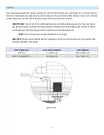
4.
ELECTRICAL
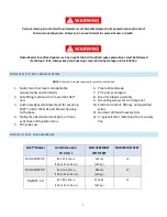
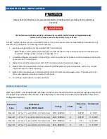
The electrical source should be within 150 ft [45 m] of the blower; consult local codes for longer wiring
distances. Wiring distances must prevent significant voltage loss. All wiring must conform to all
applicable codes (IEC, NEC, etc.). Actual power consumption varies with site conditions. All conduit and
wiring must be supplied by the contractor.
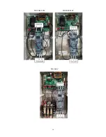
5.
CONTROLS
The control panel, which provides power to the blower, comes with an alarm system consisting of a
visual and audible alarm that will signal blower circuit failure and high motor load The control panel is
equipped with an SFR® (Sequencing Fixed Reactor) timed control feature. A manual silence button is
included.
6. INSTALLATION AND OPERATING INSTRUCTIONS
Written instructions for proper installation, use, and service of the FAST® system (manuals) are
included with the product and are available online at the BioMicrobics website. Installation of the
FAST® system must be carried out in accordance with the written instructions provided in the
Installation Manual. Moreover, all work related to the installation must be done in accordance with
local codes and regulations.
Summary of Contents for HighStrengthFAST 4.5
Page 2: ...1...
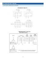
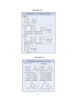
Page 15: ...12 FUJI BLOWER 1 PH FUJI BLOWER 3 PH...
Page 16: ...13 GAST BLOWER 1 PH...
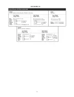
Page 19: ...16 3PH 208V 240V 1PH 208V 240V 3PH 460V...
Page 20: ...17 CONTROL PANEL SCHEMATICS...
Page 21: ...18...
Page 22: ...19...
Page 23: ...20...


