BIO-MICROBICS HighStrengthFAST 4.5 Installation Manual Download Page 25

22 


LIMITED WARRANTY 


 BioMicrobics, Inc. warrants the following systems 


RetroFAST® 0.15, 0.25, 0.375 
Residential MicroFAST® 0.5, 0.625, 0.75, 0.9, and 1.5 
BioBarriers 0.5, 1.0, 1.5, 0.5-N, 1.0-N, and 1.5-N 
STAAR® 0.5, 0.75, 1.0, 1.2, and 1.5 


against defects in materials and workmanship, for a period of two years after installation or 30 months from 

date of shipment. For all other systems and spare parts, BioMicrobics Inc. warrants against defects in materials 

and workmanship for a period of one year after installation, or eighteen months from date of shipment, 

whichever occurs first, subject to the following terms and conditions. 


TERMS AND CONDITIONS 


Note: For this warranty to be effective, BioMicrobics must have received the product


registration for the system.


During the warranty period, if any part is defective or fails to perform as specified when operating at design 
conditions, and if the equipment has been installed and is being operated and maintained in accordance with 
the written instructions that BioMicrobics, Inc. has provided, BioMicrobics, Inc. will repair or replace at its 
discretion such defective parts free of charge. Defective parts must be returned by owner to BioMicrobics, 
Inc.’s factory postage paid, if so requested. The cost of labor and all other expenses resulting from 
replacement of the defective parts and from installation of parts furnished under this warranty shall be borne 
by the owner. This warranty does not cover general system misuse, aerator components that have been 
damaged by flooding or any components that have been disassembled by unauthorized persons, improperly 
installed or damaged due to altered or improper wiring or overload protection. This warranty applies only to 
the treatment system and does not include any of the structure wiring, plumbing, drainage, septic tank or 
disposal system. BioMicrobics, Inc. reserves the right to revise, change or modify the construction and/or 
design of the BioMicrobics system, or any component part or parts thereof, without incurring any obligation to 
make such changes or modifications in present equipment. BioMicrobics, Inc. is not responsible for 
consequential or incidental damages of any nature resulting from such things as, but not limited to, defect in 
design, material, or workmanship, or delays in delivery, replacements or repairs.  


THIS WARRANTY IS IN LIEU OF ALL OTHER WARRANTIES EXPRESS OR IMPLIED. BIOMICROBICS, INC. SPECIFICALLY DISCLAIMS ANY 
IMPLIED WARRANTY OF MERCHANTABILITY OR FITNESS FOR A PARTICULAR PURPOSE. NO REPRESENTATIVE OR PERSON IS 
AUTHORIZED TO GIVE ANY OTHER WARRANTY OR TO ASSUME FOR BIOMICROBICS, INC. ANY OTHER LIABILITY IN CONNECTION WITH 
THE SALE OF ITS PRODUCTS. 

Summary of Contents for HighStrengthFAST 4.5

Page 1: ...0 r Installation Manual For use with MicroFAST 4 5 9 0 HighStrengthFAST 4 5 9 0 NitriFAST 4 5 9 0 MyFAST 1 0 Installation Manual FASTIM 002 REV 30 JUN 2022...

Page 2: ...1...

Page 3: ...ATION 7 CROSS BRACE 7 COMPONENT INSTALLATION 8 BLOWER AIR SUPPLY LINE 8 SECURING RECYCLE TROUGHS AND BLOWER AIR LINES 8 VENTING 9 BLOWER INSTALLATION 10 BLOWER WIRING DIAGRAM 11 1 AND 3 PHASE BLOWER W...

Page 4: ...wo components the treatment module and blower The blower provides air to the system via the air supply pipe The air supply pipe and draft tube create an airlift which mixes oxygen and waste throughout...

Page 5: ...3 REMOTE MOUNTED BLOWER The blower must be set in a dry stable place and its elevation must be higher than the normal flood level A two piece rectangular housing is included with the unit The dischar...

Page 6: ...LINER GASKET BAFFLE PLATE MEDIA LINER MODULE AIRLIFT TOP DIVERTER SCREEN OPTIONAL SaniTEE MIN ANCHOR WEDGES STAINLESS STEEL FOOT BOTTOM PVC PIPE NOT INCLUDED FOOT TOP 4 SCREWS BLOWER DOWNLIFT PIPE BLO...

Page 7: ...onal septic system However some basic guidelines should be followed 1 The FAST system must be located so that sufficient slope 2 in ft is provided for the influent and effluent lines 2 Excessive back...

Page 8: ...ove the FAST unit 3 Anchor wedges stainless steel for securing FAST unit to the tank and blower housing to the base 4 Piping for observation vent port air lines vent lines and leg extensions 5 PVC pip...

Page 9: ...Attach the leg extensions to the liner using supplied self tapping screws Stainless Steel hardware is required for installation 3 Carefully lower liner into tank using a jib crane or other approved m...

Page 10: ...er gasket until it hits the baffle plate Use a gasket grout mortar or bituminous sealant mastic in the tank effluent hole for a watertight seal between hole and effluent pipe CROSS BRACE 1 Use the sup...

Page 11: ...ST 1 0 The recycle troughs for this unit ship loose inside the liner 2 Insert each of the four recycle troughs through the hole in the liner Attach the recycle trough with its mounting point on the ai...

Page 12: ...iser or manhole below grade Run the vent pipe to the desired location and terminate above grade Provide a cover that meets safety standards Water accumulating in the vent piping must be drained to pre...

Page 13: ...pad using 4 supplied 14 x 1 self tapping screws Drill screws directly into blower pad 3 Connect initial blower fittings right 4 Connect airline from FAST unit to blower outlet using required piping W...

Page 14: ...11 BLOWER WIRING DIAGRAM 1 AND 3 PHASE BLOWER WIRING DIAGRAMS FPZ BLOWER 1 PH 3 PH SPENCER BLOWER 1 PH 3 PH...

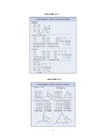
Page 15: ...12 FUJI BLOWER 1 PH FUJI BLOWER 3 PH...

Page 16: ...13 GAST BLOWER 1 PH...

Page 17: ...n blower and FAST control panel per the electrical diagram 4 BioMicrobics control panels can also be used with optional external inputs and outputs such as dry contact input and output for alarm signa...

Page 18: ...d blower based on the electrical diagram supplied for each panel specifically Note The overload amperage setting supplied for a given motor size is pre set to the appropriate place at the factory and...

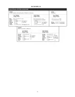
Page 19: ...16 3PH 208V 240V 1PH 208V 240V 3PH 460V...

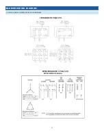
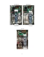
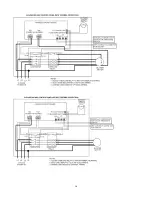
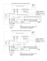
Page 20: ...17 CONTROL PANEL SCHEMATICS...

Page 21: ...18...

Page 22: ...19...

Page 23: ...20...

Page 24: ...ration of the air lift A robust splash should be present 4 Check for excessive back pressure Seal all access covers place hand about 8 in 20 cm from FAST vent If you feel air flow then there is excess...

Page 25: ...ost of labor and all other expenses resulting from replacement of the defective parts and from installation of parts furnished under this warranty shall be borne by the owner This warranty does not co...

Page 26: ...DATE __________________________________________________________________ SYSTEM DESIGNER __________________________________________________________________ SYSTEM INSTALLER ___________________________...

Reviews: