background image

#5

#6

STEP 2:

Insert and fasten 18 horizontal slide rails 

(#7)


into front grid assembly using 18 – #06 x ½ in. 
fastening screws 

(#1).


Note: Fasteners in 

bottom hole only, work from bottom row to 
top row.

Place 4 wall mount bracket 

(#06)

 over 4 rear 

verticals above 2

nd 

horizontal crossbar 

(#1)


and fasten to wall using 8 – #10 x 1¼ in.
fastening screws.

 (#2)

.

STEP 2:

Make sure unit is straight and square, and 
all verticals are pressed firmly together and 
against alignment dimples.

Note: If mounting into drywall or masonry, 
mark and drill ¼ holes and insert plastic 
wall anchors – and proceed with the 
previous step.

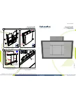
STEP 1:

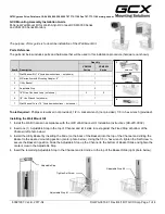
Join front to rear grid by inserting 4 front & rear grid 
connecting tubes 

(#5)

 into front grid assembly 


Note: Do not fasten at this time

STEP 3:

Turn unit upright and place firmly against 
wall where unit is to be mounted.

STEP 1:

Fasten 4 front & rear grid connecting tubes 

(#5)

 to front grid assembly using  

–  #06 x ½ in.  fastening  screws 

(#1)

.

STEP 3:

Fasten all verticals to horizontals making 
sure all joints are pressed firmly together and 
tight against alignment dimples using 48 – 
#06 x 

½

 in. fastening screws 

(#1)


Note: Fasteners in holes facing YOU only.

Unit must be attached to wall 
to keep from tipping over! 
Congratulations! We hope you 
enjoy your Bin Warehouse file 
box storage rack!

JOINING FRONT TO REAR GRID

Alignment 

dimple

FASTENING VERTICALS & FRONT & REAR GRID CONNECTING TUBES

FASTENING TO WALL

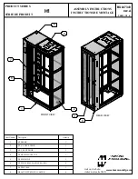
Summary of Contents for JAN21

Page 1: ...ft front right rear corner verticals 5 4 x Front and rear grid connecting tubes 6 4 x Wall mount brackets 7 18 x Horizontal slide rails Solutions Murales PROSLAT inc 225 Industriel blvd Chateauguay QC...

Page 2: ...rtical 3 Placed on horizontal crossbars holes facing down Parts needed 6 of 1 2 of 2 1 of 3 1 of 4 FRONT GRID ASSEMBLY Alignment dimples Holes down Short side to floor Top Other side Alignment dimples...

Page 3: ...EP 1 Join front to rear grid by inserting 4 front rear grid connecting tubes 5 into front grid assembly Note Do not fasten at this time STEP 3 Turn unit upright and place firmly against wall where uni...

Page 4: ...nd its successors distributors and dealers hereafter SELLER shall in no way be responsible for the product s proper use and service THE BUYER HEREBY WAIVES ALL LIABILITY CLAIMS The BUYER acknowledges...

Page 5: ...arez toutes les pi ces en diff rents groupes comme illustr Veuillez lire toutes les instructions avant de commencer le montage LISTE DES PI CES 1 12 x Barres horizontales 2 4 x Barres verticales centr...

Page 6: ...TAPE 2 Ins rez une barre verticale pour les coins arri re droit n 4 et une barre verticale pour les coins arri re gauche n 3 sur les barres horizontales trous vers le haut ASSEMBLAGE DE LA GRILLE AVA...

Page 7: ...barre transversale horizontale n 1 et fixez les au mur l aide de 8 vis de fixation 10 x 1 po n 2 TAPE 2 Assurez vous que l unit est bien droite et que toutes les barres verticales sont press es ferme...

Page 8: ...buteurs et revendeurs ci apr s VENDEUR ne doivent en aucun cas tre responsables pour l utilisation et le service de ce produit L ACHETEUR d cline toute r clamations en responsabilit L ACHETEUR reconna...

Reviews: