background image

TMC2209-V1.2 manual                        Shenzhen Biqu Technology Co., Ltd. 


7

 / 

9


voltage and the drive current can be increased. 

8、Operating Mode 

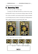
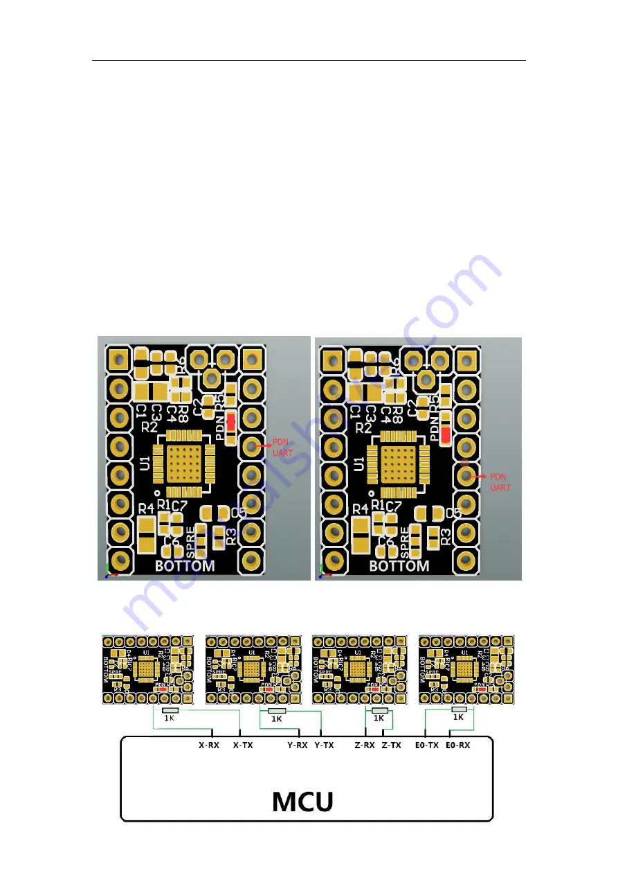
  8.1、Pin setting of UART mode 

The factory has connected the UART Pin to the fourth Pin, namely 

the PDN_UART Pin shown on the left side of the figure below. If the fifth 

Pin is used as the UART Pin, the resistance shall be removed and welded 

to the following two pads, as shown on the right side of the figure below. 

PDN is welded to select pins corresponding to UART mode


8.2、UART mode wiring diagram 


Summary of Contents for TMC2209-V1.2

Page 1: ...209 V1 2 manual Shenzhen Biqu Technology Co Ltd Shenzhen Biqu Technology Co Ltd 1 10 www BIGTREE TECH com Shenzhen Biqu Technology Co Ltd BIG TREE TECH BIGTREETECH TMC2209 V1 2 Stepper motor drive mod...

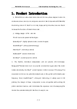
Page 2: ...t technology MicroPlyer microstep control StallGuard4 locked motor test CoolStep current dynamic control 3 The Flexible microPlyer interpolation unit can provide 256 microsteps Stallguard4 locked moto...

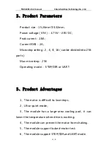
Page 3: ...4 8 16 can be divided into 256 parts Max microstep 256 Operating mode STEP DIR or UART 3 Product Advantages 1 The motor is difficult to lose steps 2 Ultra quiet mode 3 The module has a large area cool...

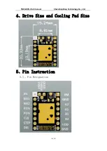
Page 4: ...TMC2209 V1 2 manual Shenzhen Biqu Technology Co Ltd 4 9 4 Drive Size and Cooling Pad Size 5 Pin Instruction 5 1 Pin Designation...

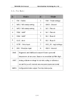
Page 5: ...PDN UART 5 B1 Phase B 6 CLK clock 6 B2 Phase B 7 STEP Pulse input 7 VCC_IO Logic voltage 8 DIR Direction input 8 GND Ground DIAG Diagnostic and StallGuard output Hi level upon stall detection or drive...

Page 6: ...2V 0 1V 3 Factory default current 0 9A 4 Potentiometer regulation instructions Rotate the potentiometer clockwise to reduce the Vref voltage and the drive current can be reduced Rotate the potentiome...

Page 7: ...ory has connected the UART Pin to the fourth Pin namely the PDN_UART Pin shown on the left side of the figure below If the fifth Pin is used as the UART Pin the resistance shall be removed and welded...

Page 8: ...ection The default mode used by the factory is mute mode as shown in the picture on the left of the following figure If anti shake mode is needed remove the resistance and weld it to the following two...

Page 9: ...g If the wrong line is connected the driver will not work directly please connect carefully as shown above 4 Do not plug and unplug the drive module when the device is working in order to avoid damage...

Reviews: