background image

BL-CB22-1214 - 04-11-2019

12-9

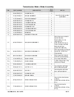
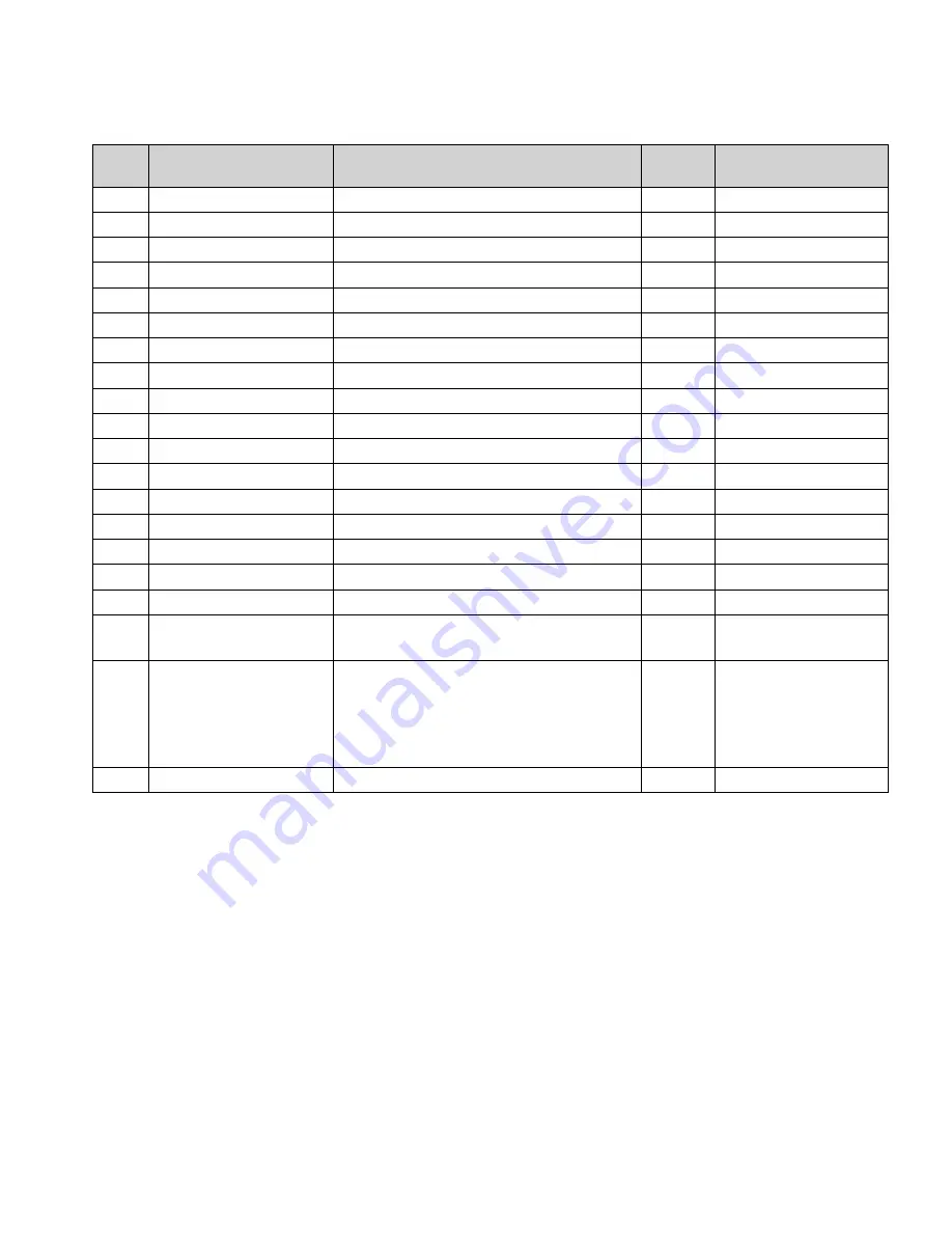
Cap Assembly - Used up to Serial Number 327120792

POS.

PART NUMBER

DESCRIPTION

QTY. 

REQD.

NOTES

1

1120-342001-00

UPPER COVER

1

2

1120-342203-00

BUTTON FOR LIFTING(R) 

1

3

1120-342202-00

BUTTON FOR LOWERING(R) 

1

4

1120-342102-00

SPRING

8

5

1120-342201-00

BUTTON BRACKET(R) 

1

6

1120-342105-00

PIN

6

7

2320-311101-00

BUTTON FOR LEANING BACK

1

8

2320-311102-00

BUTTON FOR TILTING ALONG

1

9

1120-342101-00

BUTTON BRACKET (L)

1

10

1120-342002-00

HORN BUTTON

1

10a

1120-342005-00

PIN

2

10b

1120-342003-00

SPRING

2

10c

1120-342004-00

BUTTON BRACKET

1

11

0000-000039-00

SCREW ST3.5×9.5

6

12

0000-000490-00

HARNESS CLAMP

3

13

1120-342200-00

LIFT AND LOWER BOX(R) ASSEMBLY

1

14

2320-311100-00

TILTING BOX ASSEMBLY

1

15

2320-520003-00

BUTTONS ASSEMBLY 

1

Used up to Serial # 
S2320148

15a

2320-520003-40

BUTTONS ASSEMBLY 

1

Used on Serial # 
S2221176, S2317016, 
S2320149 and between 
Serial # S2321082 and 
327120792

16

1220-560002-00

INCHING SWITCH II

5

Summary of Contents for CB22

Page 1: ...019 www bigjoeforklifts com CB22 SELF PROPELLED COUNTERBALANCED LIFT TRUCK Operation Maintenance Repair Parts List NOTE For the most current parts information and service updates please refer to the Big Joe Support site at www bigjoesupport com ...

Page 2: ...al care when operating on ramps travel slowly and do not angle or turn Travel with load downhill Do not overload truck Check nameplate for capacity and load center information When using forks space forks as far apart as load will permit Before lifting be sure load is centered forks are completely under load and load is as far back as possible against load backrest Do not handle unstable or loosel...

Page 3: ...3 5 1 5 SPEED POTENTIOMETER REPLACEMENT 5 3 5 1 6 BELLY BUTTON SWITCH REPLACEMENT 5 3 5 1 7 HORN SWITCH REPLACEMENT 5 3 5 1 8 LIFT AND LOWER SWITCH REPLACEMENT 5 4 5 1 9 TILT SWITCH REPLACEMENT 5 6 5 2 STEERING ARM 5 6 5 2 1 RETURN SPRING REPLACEMENT 5 6 5 2 2 STEERING ARM REMOVAL 5 6 5 2 3 STEERING ARM INSTALLATION 5 6 5 3 COMPARTMENT COVERS 5 6 5 3 1 REMOVAL 5 6 5 3 2 INSTALLATION 5 6 6 BRAKE SE...

Page 4: ...NANCE 10 1 10 1 2 CLEANING 10 1 10 1 3 PANEL REMOVAL 10 1 10 1 4 PANEL DISASSEMBLY 10 1 10 1 5 PANEL INSTALLATION 10 1 10 2 HORN REPLACEMENT 10 1 10 3 PUMP MOTOR 10 5 10 4 DRIVE MOTOR 10 5 10 4 1 MOTOR REMOVAL 10 5 10 4 2 MOTOR INSTALLATION 10 5 10 5 DEADMAN SWITCH 10 5 10 5 1 REPLACEMENT 10 5 11 OPTIONAL EQUIPMENT 11 1 12 ILLUSTRATED PARTS BREAKDOWN 12 1 ...

Page 5: ...ruck can be driven with forks raised or lowered however the speed is restricted when the platform is raised above a preset limit The model number will be found on the name plate Figure 1 1 along with the serial number lifting capac ity and load center Figure 1 2 shows the locations of the truck s main components and controls 1 3 SAFETY FEATURES The CB22 is designed and engineered to provide max im...

Page 6: ... Lift Truck R6898 ITEM COMPONENT 1 Chassis 2 Cover 3 Drive wheel 4 Cover 5 Control Handle 6 Battery Indicator 7 Key Switch 8 Front cover 9 Mast 10 Back Rest 11 Forks 12 Load Wheel 13 Hydraulic pump 14 Battery 15 Battery Disconnect ITEM COMPONENT ...

Page 7: ...by a qualified person on a regular basis Do not exceed the rated capacity Overloading may result in damage to the hydraulic system and struc tural components Be certain that the lifting mechanism is operating smoothly throughout its entire height both empty and loaded Be sure that mast is vertical do not operate on a side slope Be sure the truck has a firm and level footing Avoid overhead wires an...

Page 8: ...een restored to a safe operating condition Do not make any unauthorized repairs or adjustments All service must be performed by a qualified maintenance technician Table 2 1 Operator Checks ITEM PROCEDURE Transmission and hydraulic systems Check for signs of fluid leakage Forks Check for cracks and damage and that they are properly secured Chains cables and hoses Check that they are in place secure...

Page 9: ...BL CB22 1214 04 11 2019 2 3 Figure 2 2 Sample of Operator Check List R6479 ...

Page 10: ... slowing or stopping the truck 5 Procedures for movement in reverse are the same as in the forward direction except slowly press the speed control backward See Figure 2 3 2 5 1 Stopping The brake pattern of the truck depends on the ground conditions The driver must take this into account when operating the truck The driver must be looking ahead when traveling If there is no hazard brake moderately...

Page 11: ...s push in the LOWER button and hold until forks descend to desired height 2 9 TILT CONTROLS Tilt Control buttons are located on the steering control head Figure 2 4 To tilt forks back push in the TILT BACK button and hold until forks reach desired angle To tilt the forks for ward push in the TILT FORWARD button and hold until forks descend to desired angle 2 10 LOADING AND UNLOADING 1 Move truck t...

Page 12: ...2 6 BL CB22 1214 04 11 2019 NOTES ...

Page 13: ... affected A baking soda solution one pound to one gallon of water applied to spilled acid until bub bling stops neutralizes the acid for safe handing and disposal Leakage voltage from battery terminals to battery case can cause misleading trouble symptoms with the truck electrical system Since components of the truck elec trical system are insulated from truck frame leakage voltage will not normal...

Page 14: ...s formed during charging is highly explosive and can cause seri ous injury 1 Charge the battery only in areas designated for that use 2 Make certain the charger being used matches the voltage and amperage of the truck battery 3 Before disconnecting or connecting batteries to a charger make sure the charger is OFF If an attempt is made to do this while the charger is ON serious injury to you the ba...

Page 15: ...eing a valve regulated battery it never requires watering 3 4 CHARGING BATTERIES Charging requirements will vary depending on depth of discharge and temperature Follow safety rules when placing a battery on charge Proceed as follows 1 Park truck at charging station with carriage low ered and turn the key switch off 2 Check the condition of the AC cord the battery connector and battery cables If th...

Page 16: ...ing freely With lift carriage fully lowered spray or brush on a film of SAE 30 or 40 engine oil Table 3 2 Recommended Lubricants See Table 3 3 for Application No 1 Transmission oil EP SAE 80W 90 Transmission oil EP SAE 10W 30 Note No 2 Grease Lithium base general purpose No 3 Hydraulic oil Heavy duty with a viscosity of 150 SUS foam suppressing agent and rust and oxidation inhibitors Hydraulic oil...

Page 17: ...er Mast Brush No 2 Full length of channel where rollers operate 2 Lift Chain Brush or Spray No 4 See Paragraph 3 6 3 Lift Carriage Brush No 2 Light coating where forks slide 4 Hydraulic Reservoir Capacity 1 quarts Can No 3 With lift carriage fully lowered fill reservoir with hydraulic oil to 1 inch below opening 5 Transmission Capacity 2 pints Can No 1 Fill to level plug opening R6901 ...

Page 18: ...3 6 BL CB22 1214 04 11 2019 NOTES ...

Page 19: ... travel forward or reverse All other functions operate normally a Check all wiring A loose con nection may be the cause of malfunction Tighten all loose connections before further troubleshooting b Defective deadman switch 29 Figure 12 1 Check and replace switch if defective c Defective main contactor 10 Figure 12 31 or 9 Figure 12 32 Check for proper operation and replace if necessary d Defective...

Page 20: ...se c Defective mast or carriage roll ers Replace rollers Forks do not lift to top a Oil level too low Add oil to reservoir b Load larger than capacity Refer to I D plate for capacity Weak slow or uneven action of hydraulic system a Defective pump or relief valve Check pressure Adjust as necessary b Worn lift cylinder Replace cylinder c Load larger than capacity Refer to I D plate for capacity d De...

Page 21: ...acity c Batteries need charging Change batteries Forks creep downward under load when in a raised position Leak in hydraulic system lift cylin der or lowering valve Check for leaking fitting in hydraulic line and repair as required Repack lift cylinder or replace or repair valve assembly 21 Figure 12 18 MISCELLANEOUS Steering arm does not return to the upright position a Week return spring Replace...

Page 22: ...n the latest event of every alarm occurred This function permits a deeper diagnosis of problems as the recent history can be revisited 4 2 2 2 Logbook Access To view the alarm logbook proceed as follows 1 Connect the Zapi Handset refer to paragraph 4 2 1 2 Press the ROLL down button 1 Figure 4 2 and the ENTER button 3 at the same time to enter the MAIN MENU 3 Press the ROLL down button 2 or the RO...

Page 23: ...options Figure 4 2 Zapi Handset Table 4 2 Set Options R6624 Parameter Factory Setting Description TILLER switch HANDLE This option handles the input CNB 3 Table 4 5 This input opens when the operator leaves the truck released It is connected to a Keyswitch controlled voltage when the operator is present SET INPUT 1 OPTION 1 Standard Version only This option handles the digital input CNA 15 It can ...

Page 24: ...ervice brake of the exclusive hydro becomes active when CNB 7 is opened HOUR COUNTER RUNNING This option specifies the hour counter mode It can be set as RUNNING The counter registers travel time only key on The counter registers when the keyswitch is closed BATTERY CHECK Level 1 This option specifies the handling of the low battery charge detec tion It can be set as Level 0 Nothing happens the ba...

Page 25: ...age is equal less than the SET POT BRK MIN the minimum release braking strength is applied following the RELEASE BRAKING setting When the pedal potentiometer voltage is equal higher than the SET POT BRK MAX the maximum release braking strength is applied following the PEDAL BRAKING setting In the intermedi ate position the electrical braking strength is a linear function between the minimum RELEAS...

Page 26: ...ads down to the specified percentage PERFORMANCE OPTION 1 This option can be set OPTION 1 OPTION 2 QUICK INV LOGIC OPTION 1 This option specifies the active level for the Belly switch input CNB 7 OPTION 1 The quick inversion is executed when CNB 7 Table 4 5 is closed to a Keyswitch controlled voltage OPTION 2 The quick inversion is executed when CNB 7 Table 4 5 is opened from a Keyswitch controlle...

Page 27: ...ing Description SET POT BRK MIN 0 5 V This setting records the minimum value of braking pedal potentiom eter when the braking pedal switch is closed the procedure is similar to the PROGRAM VACC function This procedure must be carried out only if the PEDAL BRAKING option is programmed as ANALOG No adjustment is necessary when PEDAL BRAKING options is programmed as NONE SET POT BRK MAX 4 5 V This se...

Page 28: ...t percent of the Maximum truck speed The rela tionship between the accelerator position and the truck speed is linear between the THROTTLE 0 ZONE and the X point and also between the X point and the maximum accelerator position but with two different slopes Figure 4 4 ADJUSTMENT 01 LEVEL 5 Adjust the upper level of the battery charge table Level 0 to 9 ADJUSTMENT 02 LEVEL 5 Adjust the lower level ...

Page 29: ... a long time to accelerate RELEASE BRAKING LEVEL 5 Level 0 to 9 It controls the deceleration ramp when the travel request is released At Level 9 the truck brakes abruptly INVERS BRAKING LEVEL 4 Level 0 to 9 It controls the deceleration ramp when the direction switch is inverted during travel At Level 9 the truck brakes abruptly PEDAL BRAKING LEVEL 9 Level 0 to 9 It controls the deceleration ramp w...

Page 30: ...peed applied when the forward or reverse switch is closed but the accelerator at its minimum In the ACO sense Coils this setting is higher equal than 5 Hz RPM CREEP 100 A Percentage value Set to 100 and not Used MAXIMUM CURRENT 96 It specifies the percentage of the absolute current 150A at which the current will be limited Normally MAXIMUM CURRENT is 100 DO NOT CHANGE INCHING SPEED 0 Hz Hz value I...

Page 31: ...es the load to Batt Maximum current 3 A CNA 4 NPC Negative of pump contactor soil CNA 5 PPC PEV Positive of pump contactor coil and lowering electrovalve coil CNA 6 NEV Negative of the lowering electrovalve coil CNA 7 CAN LOW Low level CAN BUS voltage I O CNA 8 BAT Bat CNA 9 ENC Encoder Positive Supply 5 or 12 Vdc CNA 10 ENC Encoder Negative Supply GND to minus battery CNA 11 HM B Output for drivi...

Page 32: ...nted on the AC 0 cover CNB 2 CM Common for FW BW SR1 SR2 TILLER H S BELLY LIFTING LOWERING microswitches This connection supplies a keyswitch voltage level CNB 3 TILLER SW Tiller request input Must be connected to the tiller microswitch active high CNB 4 H S SW Hard Soft request input Must be connected to the Hard Soft microswitch active high CNB 5 BACKWARD SW Backward direction request input Must...

Page 33: ...ception CNC 2 NCLRXD Negative serial reception CNC 3 PCLTXD Positive serial transmission CNC 4 NCLTXD Negative serial transmission CNC 5 GND Negative console power supply CNC 6 12V Positive console power supply CNC 7 FLASH Must be connected to C8 for the Flash memory programming if used CNC 8 FLASH Must be connected to C7 for the Flash memory programming If used ...

Page 34: ...4 16 BL CB22 1214 04 11 2019 NOTES ...

Page 35: ...1 CONTROL HEAD 5 1 1 Cap Assembly Removal 1 Turn off the key switch 12 Figure 12 29 or 12 Figure 12 30 and disconnect the batteries 2 Remove four screws 17 Figure 5 1 lift up cap assembly 1 and disconnect harness 15 Figure 5 4 from harness 28 Figure 5 2 Figure 5 1 Control Head R6877A ...

Page 36: ...embly 1 Figure 5 1 in place and connect harness to harness 28 Figure 5 2 2 Position cap assembly 1 Figure 5 1 on control head and secure with four screws 17 3 Reconnect the batteries and turn on the key switch 12 Figure 12 29 or 12 Figure 12 30 Figure 5 2 Steering Arm R6876A ...

Page 37: ... new potentiometer 21 in bracket 20 and secure with screw 16 lock washer 6 and flat washer 7 8 Install screw 22 lock washer 6 and flat washer 7 9 Install control knob 14 on potentiometer 21 and secure with screw 4 and washer 3 10 Install control knob 2 on the other side of poten tiometer 21 and secure with screw 4 and washer 3 11 Connect harness 28 Figure 5 2 to potentiome ter 21 Figure 5 1 12 Ins...

Page 38: ... secure with three screws 11 7 Install the cap assembly as described in para graph 5 1 2 5 1 8 Lift and Lower Switch Replacement 1 Remove the cap assembly as described in para graph 5 1 1 2 Remove switch assembly 13 Figure 5 4 from cap 1 3 Remove pin 6 Figure 5 4 securing bracket 5 and remove the bracket 4 Remove two pins 6 two switches and four springs 4 from bracket 5 R6810A ...

Page 39: ...BL CB22 1214 04 11 2019 5 5 Figure 5 4 Cap Assembly R6878A ...

Page 40: ...teering arm being sure it fully engages its seat 7 Position the opposite end of the gas return spring 3 on bracket 17 and install screw 4 8 Install middle cover 5 Figure 12 7 and secure with two screws 4 9 Reconnect the batteries and turn on the key switch 12 Figure 12 29 or 12 Figure 12 30 5 2 2 Steering Arm Removal 1 Turn off the key switch 12 Figure 12 29 or 12 Figure 12 30 and disconnect the b...

Page 41: ...agraph 5 3 4 Remove the steering arm as described in para graph 5 2 2 5 Disconnect electric brake 2 Figure 6 1 from the harness 1 Figure 12 34 or 1 Figure 12 35 6 Remove three screws 1 Figure 6 1 and remove brake 2 7 Place the new brake into position and secure with the three screws 1 8 Reconnect electric brake 2 to the harness 1 Figure 12 34 or 1 Figure 12 35 9 Install the steering arm as describ...

Page 42: ...6 2 BL CB22 1214 04 11 2019 Figure 6 1 Transmission Motor Brake Assembly R6879A ...

Page 43: ... 12 Figure 7 1 and remove the six screws 7 six lock washers 8 and six flat washers 9 8 Slowly lower the transmission out the bottom of the frame 9 Install new transmission by reversing the steps above 7 3 Load Wheel 7 3 1 Removal 1 Turn off the key switch 12 Figure 12 29 or 12 Figure 12 30 and disconnect the batteries 2 Block the drive wheel to prevent the truck from rolling 3 Jack up the truck to...

Page 44: ...7 2 BL CB22 1214 04 11 2019 Figure 7 1 Transmission Motor Brake Assembly R6879A ...

Page 45: ...BL CB22 1214 04 11 2019 7 3 Figure 7 2 Load Wheels R6882A ...

Page 46: ...7 4 BL CB22 1214 04 11 2019 NOTES ...

Page 47: ... mast 18 Figure 8 2 to allow for adjustment of middle jam nuts 4 Break the lower jam nuts 2 Figure 8 1 located below the mounts on outer mast free from the middle jam nuts 2 5 Take up slack in both lift chains with middle jam nut 2 Strive for equal tension on both chains 6 Align adjusting bolts 1 so each clevis pin 4 is parallel to the mast CAUTION At least 3 full threads must be present below low...

Page 48: ...8 2 BL CB22 1214 04 11 2019 Figure 8 2 Elevation System Telescopic R6883 ...

Page 49: ...wer is disconnected 3 Loosen jam nuts 2 Figure 8 1 above the mount of outer mast 25 Figure 8 3 to allow for adjust ment of middle jam nut 4 Break the lower jam nuts 2 Figure 8 1 located below the mount of outer mast free from the mid dle jam nuts 5 Take up slack in both lift chains with middle jam nut 2 Strive for equal tension on both chains 6 Align anchors 1 so each clevis pin 4 is parallel to t...

Page 50: ...8 4 BL CB22 1214 04 11 2019 Figure 8 3 Mast TRIMAST R6884A ...

Page 51: ... 8 1 and clevis pin 4 connecting chain 5 to chain anchor 6 at the lift carriage 5 Remove cotter pin 3 and clevis pin 4 connect ing chain 5 to chain anchor 1 at free lift cylinder 8 Figure 8 3 6 Remove chain from sheave 7 7 Position new chain on sheave 7 8 Secure chain to chain anchor 1 at free lift cylin der 8 with clevis pin 4 and cotter pin 3 9 Connect the opposite end of chain to chain anchor 6...

Page 52: ...8 6 BL CB22 1214 04 11 2019 NOTES ...

Page 53: ...to bring to proper level Use hydraulic oil listed in Table 3 2 9 Install the front compartment covers as described in paragraph 5 3 9 2 HYDRAULIC PUMP AND MOTOR ASSY WARNING When forks are raised pressure exists in the hydraulic system lines and fittings To ensure release of pressure forks must be fully lowered and the batteries discon nected before performing any mainte nance on the hydraulic sys...

Page 54: ...9 2 BL CB22 1214 04 11 2019 Figure 9 1 Hydraulic System R8009 ...

Page 55: ...ucks Reconnect hose 5 Figure 9 3 to pump and motor 5 Figure 9 1 4 Connect electrical leads to pump and motor 5 5 Fill the hydraulic reservoir Use hydraulic oil listed in Table 3 2 6 Reconnect the batteries and turn on the keyswitch 12 Figure 12 29 or 12 Figure 12 30 7 Operate the lift and lower buttons to refill the cylinder and lines with hydraulic oil 8 Check level of hydraulic oil If required a...

Page 56: ...9 4 BL CB22 1214 04 11 2019 Figure 9 3 Hydraulic System TRIMAST R6888A ...

Page 57: ...mping lightly at the base of the cylinder 2 Remove gland nut 7 Figure 9 5 3 Remove wiper ring 8 and O ring 9 from gland nut 7 4 Pull out piston rod 1 5 Remove bushing and bearing 4 6 Remove piston 2 and clip 3 from rod 1 7 Remove packing 11 and backup ring 10 from piston 1 8 Coat all parts with hydraulic oil Table 3 2 9 Install packing 11 and backup ring 10 on piston 1 10 Install new clip 3 on rod...

Page 58: ...9 6 BL CB22 1214 04 11 2019 Figure 9 4 Elevation System Telescopic R6883A ...

Page 59: ...BL CB22 1214 04 11 2019 9 7 Figure 9 5 Lift Cylinder Telescopic R6889A ...

Page 60: ...ecure the lift cylinder in a vise clamping lightly at the base of the cylinder 2 Remove gland nut 4 Figure 9 7 3 Remove wiper 1 collar 2 packing 3 and O ring 5 from gland nut 4 4 Pull out piston rod 6 5 Remove ring 7 from piston rod 6 6 Coat all parts with hydraulic oil Table 3 2 7 Install ring 7 on piston rod 6 8 Insert rod 6 in cylinder tube 8 9 Install O ring 5 wiper 1 collar 2 and packing 3 on...

Page 61: ...BL CB22 1214 04 11 2019 9 9 Figure 9 6 Elevation System TRIMAST R6884A ...

Page 62: ...9 10 BL CB22 1214 04 11 2019 Figure 9 7 Free Lift Cylinder TRIMAST R6890A ...

Page 63: ...9 8 3 Remove wiper 1 packing 2 and O rings 4 and 11 from gland nut 3 4 Pull out piston rod 5 5 Remove backup ring 8 retaining ring 7 and bushing 6 from piston rod 5 6 Coat all parts with hydraulic oil Table 3 2 7 Install backup ring 8 retaining ring 7 and bush ing 6 on piston rod 5 8 Insert rod 5 in cylinder tube 9 9 Install wiper 1 packing 2 and O rings 4 and 11 on gland nut 3 10 Install gland nu...

Page 64: ...9 12 BL CB22 1214 04 11 2019 Figure 9 8 Secondary Lift Cylinder TRIMAST R6891 ...

Page 65: ...e certain power is disconnected CAUTION Hydraulic oil can damage parts Wipe off any oil immediately Provide a container under the line or fitting before discon necting 3 Remove the front compartment covers as described in paragraph 5 3 4 Disconnect hoses 13 Figure 9 1 from the tilt cyl inder 5 Support the tilt cylinder and remove bolts 1 Fig ure 9 9 lock washers 2 flat washers 3 and pins 4 and sha...

Page 66: ...n cylinder body 17 13 Install dust seal 7 O ring 8 snap ring 9 seal 10 O ring 13 and bearing 12 in gland nut 11 14 Install gland nut 11 in tube 17 15 Install retaining rings 3 and bearing 2 in clevis 1 16 Install clevis 1 on piston rod 14 and secure with bolt 4 lock washer 5 and nut 6 9 5 4 3 Installation 1 Position the cylinder between the outer mast and the truck frame 2 Secure the cylinder with...

Page 67: ...BL CB22 1214 04 11 2019 9 15 Figure 9 10 Tilt Cylinder R6893 ...

Page 68: ...9 16 BL CB22 1214 04 11 2019 NOTES ...

Page 69: ... 4 Make sure the connections to the buss bars are tight Use two well insulated wrenches for this task in order to avoid contacting the buss bars 10 1 3 Panel Removal 1 Turn off the key switch 12 Figure 12 29 or 12 Figure 12 30 and disconnect the batteries 2 Remove the compartment covers as described in paragraph 5 3 3 Tag and disconnect all electrical cables which connect to the control panel 5 Fi...

Page 70: ...10 2 BL CB22 1214 04 11 2019 Figure 10 1Electrical System Used up to Serial S2320148 R6478 R6894A ...

Page 71: ...BL CB22 1214 04 11 2019 10 3 Figure 10 2 Electrical System Used from Serial S2320149 R6478 R6894A ...

Page 72: ...10 4 BL CB22 1214 04 11 2019 Figure 10 3 Electrical Panel R6478 R6895A ...

Page 73: ... the shaft of motor 3 2 Install drive motor onto transmission Make sure the gears align 3 Reinstall eight screws 4 eight lock washers 5 and eight flat washers 6 to secure the motor to the transmission 4 Install brake plate 17 Figure 12 1 on the motor and secure with three screws 26 and three lock washers 27 5 Position cables as noted in removal and recon nect cables to the drive motor 6 Reinstall ...

Page 74: ...10 6 BL CB22 1214 04 11 2019 Figure 10 4 Transmission Motor Brake Assembly R6879A ...

Page 75: ...BL CB22 1214 04 11 2019 11 1 SECTION 11 OPTIONAL EQUIPMENT ...

Page 76: ...11 2 BL CB22 1214 04 11 2019 NOTES ...

Page 77: ...BL CB22 1214 04 11 2019 12 1 SECTION 12 ILLUSTRATED PARTS BREAKDOWN Following is an illustrated parts breakdown of assemblies and parts associated with the CB22 Lift Truck ...

Page 78: ...12 2 BL CB22 1214 04 11 2019 Figure 12 1 Steering System R6876A ...

Page 79: ... LOCKWASHER Ø5 3 14 0000 000390 00 FLATWASHER Ø5 3 15 0000 000004 00 SCREW M5 12 2 16 1120 300004 00 FIXED PLATE 1 17 1120 300001 0A BRAKE BASE 1 18 1120 300006 00 SPACER 1 19 0000 000088 00 SCREW M4 8 2 20 0000 000122 00 LOCKWASHER Ø4 3 21 0000 000377 00 SCREW M2 20 2 22 0000 000378 00 SCREW M4 16 1 23 0000 000702 00 FLATWASHER Ø4 1 24 0000 000491 00 PLASTIC RING 1 25 0000 000209 00 NUT M4 1 26 0...

Page 80: ...12 4 BL CB22 1214 04 11 2019 Figure 12 2 Control Head Used up to Serial Number 327120792 R6877A ...

Page 81: ...51 00 SCREW M8 25 2 12 0000 000159 00 LOCKWASHER Ø8 2 13 0000 000176 00 FLATWASHER Ø8 2 14 1120 340003 00 CONTROL KNOB LEFT 1 15 1120 343000 00 BELLY BUTTON COVER ASSEMBLY 1 Without Wire Harness 16 0000 000004 00 SCREW M5 12 2 17 0000 000035 00 SCREW M5 20 4 18 1120 340002 00 COVER 1 19 1120 341000 00 HANDLE 1 20 1120 340001 00 CONNECTOR BRACKET 1 21 1220 520008 0C ACCELERATOR ASSEMBLY 1 22 0000 0...

Page 82: ...12 6 BL CB22 1214 04 11 2019 Figure 12 3 Control Head Used from Serial Number 327120793 DE_0048 ...

Page 83: ...ING 2 6 1115 340004 00 CONTROL KNOB LEFT 1 7 1220 520008 0C ACCELERATOR ASSEMBLY 1 8 0000 000323 00 SCREW M5 16 1 9 0000 000390 00 FLATWASHER Ø5 1 10 1115 340007 00 WIRE HARNESS COVER 1 11 1120 520009 00 REVERSING SWITCH WIRE 1 12 0000 000989 00 SCREW M2 12 2 13 1115 340003 00 COVER 1 14 1121 310004 00 SPRING 2 15 1115 340002 00 COVER 1 16 0000 000322 00 SCREW M8 25 4 17 0000 000159 00 LOCKWASHER ...

Page 84: ...12 8 BL CB22 1214 04 11 2019 Figure 12 4 Cap Assembly Used up to Serial Number 327120792 R6878A ...

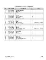
Page 85: ...2 00 BUTTON FOR TILTING ALONG 1 9 1120 342101 00 BUTTON BRACKET L 1 10 1120 342002 00 HORN BUTTON 1 10a 1120 342005 00 PIN 2 10b 1120 342003 00 SPRING 2 10c 1120 342004 00 BUTTON BRACKET 1 11 0000 000039 00 SCREW ST3 5 9 5 6 12 0000 000490 00 HARNESS CLAMP 3 13 1120 342200 00 LIFT AND LOWER BOX R ASSEMBLY 1 14 2320 311100 00 TILTING BOX ASSEMBLY 1 15 2320 520003 00 BUTTONS ASSEMBLY 1 Used up to Se...

Page 86: ...12 10 BL CB22 1214 04 11 2019 Figure 12 5 Cap Assembly Used from Serial Number 327120793 DE_0049 ...

Page 87: ...7 2320 311101 00 BUTTON FOR TILTING BACK 1 8 2320 311102 00 BUTTON FOR TILTING FORWARD 1 9 1120 342101 00 BUTTON BRACKET L 1 10 1120 342300 00 HORN BUTTON ASSEMBLY 1 11 0000 000039 00 SCREW ST3 5 9 5 6 12 0000 000490 00 HARNESS CLAMP 3 13 1120 342200 00 LIFT AND LOWER BOX R ASSEMBLY 1 14 2320 311100 00 TILTING BOX ASSEMBLY 1 15 2320 520003 40 BUTTONS ASSEMBLY 1 16 1220 560002 00 INCHING SWITCH II ...

Page 88: ...12 12 BL CB22 1214 04 11 2019 Figure 12 6 Emergency Reverse Switch Assembly Used up to Serial Number 327120792 R6810A ...

Page 89: ...CRIPTION QTY REQD NOTES 1120 343000 00 B EMERGENCY REVERSE SWITCH ASSY 1 Includes Pos 1 6 1 1120 343002 00 COVER 1 2 1120 343003 00 SPRING 2 3 1120 342005 00 PIN 2 4 1120 343001 0A BRACKET 1 5 1120 343004 00 PIN 1 6 1220 520005 0C EMERGENCY REVERSE SWITCH WIRE HARNESS 1 With Switch 7 1220 560002 00 INCHING SWITCH II 1 ...

Page 90: ...12 14 BL CB22 1214 04 11 2019 Figure 12 7 Transmission Motor Brake Assembly R6879A ...

Page 91: ...0 10 but you have to change the Drive Motor Gear set to part 4230 GB10 00 12a 4230 210000 10 GEAR BOX ASSEMBLY II 1 ZK10 Used between Serial S2214169 327121134 Serviceable 12b ZK12 240000 A0 GEAR BOX ASSEMBL 1 ZK12 Used from Serial 327121135 Serviceable 13 1120 200001 00 DRIVE WHEEL 1 Poly wheel Standard 13a 1120 200001 20 DRIVE WHEEL 1 Traction Drive Wheel Poly Diamond X Siped 14 0000 000025 00 L...

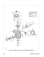
Page 92: ...12 16 BL CB22 1214 04 11 2019 Figure 12 8 Transmission Used between Serial S2214169 327121134 R8018 ...

Page 93: ...0961 00 BEARING 2 9 1120 240005 30 PLUG 1 10 1120 GB30 10 GEAR RING SET 1 This set includes 2 gears 11 1120 240007 30 WASHER 1 12 1120 240008 30 LOCKING PLATE 1 13 0000 000277 00 BOLT M8 25 3 14 0000 001054 00 BEARING 30204 2 15 4230 GB10 00 GEAR SET z1 z2 26 100 1 This set includes 2 gears 16 0000 000379 00 FLATWASHER Ø14 1 17 0000 001055 00 WASHER Ø14 1 18 0000 001056 00 NUT M14 1 5 1 19 0000 00...

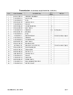
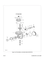
Page 94: ...12 18 BL CB22 1214 04 11 2019 Figure 12 9 Transmission Used from Serial 327121134 DE_0050 ...

Page 95: ...00 BEARING 2 9 ZK12 240017 00 PLUG 1 10 ZK12 GB30 10 GEAR RING SET 1 This set includes 2 gears 11 ZK12 240015 00 WASHER65X36 5X3 1 12 ZK12 240021 00 WASHER Ø36 1 13 3030 110000 06 NUT M36 3 14 0000 001054 00 BEARING 2 15 ZK12 GB30 A0 GEAR SET Z1 Z2 26 100 1 This set includes 2 gears 16 0000 000379 00 FLATWASHER Ø14 1 17 ZK12 240020 00 WASHER Ø14 1 18 3030 070000 04 NUT M14 1 19 0000 000211 00 O RI...

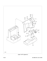
Page 96: ...12 20 BL CB22 1214 04 11 2019 Figure 12 10 Compartment R6880 ...

Page 97: ...125 140002 00 UPPER COVER 1 Used up to serial number 326110893 3a 2125 140002 50 UPPER COVER 1 Used from serial number 326110894 4 0000 000126 00 SCREW M6 16 2 5 1120 150002 00 MIDDLE COVER 1 6 2125 140001 00 LOWER COVER 1 7 1146 151002 30 MANUAL HOLDER 1 Used from serial number 326110894 8 0000 000119 00 SCREW M5x12 4 9 0000 000546 00 NUT M5 4 ...

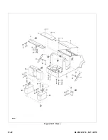
Page 98: ...12 22 BL CB22 1214 04 11 2019 Figure 12 11 Frame R6881 ...

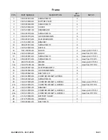
Page 99: ...REW M6 10 4 Used up to 01 15 13 13a 0000 000179 00 SCREW M6 10 4 Used from 01 15 13 14 2320 110000 00 FRAME 1 Used up to 07 15 12 14a 2320 110000 0A FRAME 1 Used from 07 15 12 15 0000 000373 00 FLATWASHER Ø12 8 16 0000 000060 00 LOCKWASHER Ø12 8 17 0000 000623 00 BOLT M12 30 8 18 2320 140000 00 COUNTER WEIGHT UPPER 1 19 0000 000026 00 SCREW M8 30 2 20 2320 120000 00 COUNTER WEIGHT LOWER I 1 Used u...

Page 100: ...12 24 BL CB22 1214 04 11 2019 Figure 12 12 Load Wheels R6882A ...

Page 101: ...0000 000620 00 BOLT M6 16 2 4 0000 000056 00 LOCKWASHER Ø6 2 5 0000 000380 00 FLATWASHER Ø6 2 6 2320 600002 00 BAFFLE 1 7 2320 601100 00 LOADING WHEEL 1 8 2320 600001 00 BRACKET 1 9 0000 000379 00 FLATWASHER Ø14 2 10 0000 000233 00 LOCKWASHER Ø14 2 11 0000 001028 00 BOLT M14 90 2 12 0000 000858 00 BUSHING 50 60 30 1 13 0000 000857 00 BEARING 2 ...

Page 102: ...12 26 BL CB22 1214 04 11 2019 Figure 12 13 Elevation System Telescopic ...

Page 103: ...0 1 10 0000 000060 00 LOCKWASHER Ø12 3 11 0000 000373 00 FLATWASHER Ø12 3 12 2125 600003 00 POSITIONING HARNESS 1 13 2125 600002 00 CHAIN ROLLER 2 14 2125 600001 00 CHAIN WHEEL BRACKET 1 15 2125 650001 00 CYLINDER HOOP 1 16 2125 650003 00 HOOP BUSHING Ø8 150 1 17 2110 410000 00 02 LIFTING CYLINDER ASSEMBLY 1 This Is Used For Lift Height 104 17a 2110 410000 00 05 LIFTING CYLINDER ASSEMBLY 1 This Is...

Page 104: ...12 28 BL CB22 1214 04 11 2019 Figure 12 14 Elevation System Telescopic Continued R6883A ...

Page 105: ...2120003 35 0000 000122 00 LOCKWASHER Ø4 2 Used up to Serial S2120003 36 0000 000139 00 NUT M4 2 Used up to Serial S2120003 37 2125 520003 0C PROXIMITY SWITCH ASSEMBLY 1 Used up to Serial S2120003 38 0000 000117 00 SCREW M5 10 4 39 2125 500003 00 PROXIMITY SWITCH 1 40 2125 520009 26 LIFTING PROXIMITY SWITCH WIRE 1 This Is Used For Lift Height 104 40a 2125 520009 29 LIFTING PROXIMITY SWITCH WIRE 1 T...

Page 106: ...12 30 BL CB22 1214 04 11 2019 Figure 12 15 Elevation System Three Stage R6884A ...

Page 107: ... 15 0000 000284 00 BOLT M12 30 4 16 0000 000060 00 LOCKWASHER Ø12 2 17 0000 000373 00 FLATWASHER Ø12 2 18 0000 000517 00 BOLT M12 50 1 19 0000 000427 00 FLATWASHER Ø12 1 20 2125 600002 30 CHAIN ROLLER 1 21 2125 600003 30 BUSHING 1 22 2125 620000 30 01 MIDDLE MAST ASSEMBLY 1 Used for Lift Height 157 23 2125 612000 00 ROLLER ASSEMBLY 8 24 0000 000244 00 BOLT M10 30 4 25 2320 610000 30 01 OUTER MAST ...

Page 108: ...12 32 BL CB22 1214 04 11 2019 Figure 12 16 Elevation System Three Stage Continued R6884A ...

Page 109: ... BRACKET 1 36 0000 000117 00 SCREW M5 10 8 37 2125 500001 3A SENSOR BRACKET 1 Used up to serial number 324170306 37a 2333 500001 30 SENSOR BRACKET 1 Used from serial number 324170307 38 2125 520003 3A LOWER PROXIMITY SWITCH WIRE 1 39 2125 520009 22 LIFTING PROXIMITY SWITCH WIRE 1 Used from 113011 40 2125 500003 00 PROXIMITY SWITCH 1 41 0000 000546 00 NUT M5 8 42 0000 000206 00 LOCKWASHER Ø5 8 43 0...

Page 110: ...12 34 BL CB22 1214 04 11 2019 Figure 12 17 Lift Carriage Two Stage R6815A ...

Page 111: ...KREST 1 Used up to 051512 4a 2320 631000 00 LOAD BACKREST 1 Used from 051612 5 2125 631104 00 SCREW 4 6 2125 612007 00 SNAP RING 4 7 2125 612002 00 ASSISTANT ROLLER 4 8 2125 612001 00 MAIN ROLLER 4 9 2125 612005 00 DUST SNAP 4 10 0000 000183 00 RETAINER RING Ø35 4 11 2125 631000 00 FORK FRAME 1 12 2125 630001 00 FORK 2 13 2125 630001 10 PIN ASSEMBLY 2 14 2125 631100 00 ROLLER ASSEMBLY 4 15 0000 00...

Page 112: ...12 36 BL CB22 1214 04 11 2019 Figure 12 18 Lift Carriage Three Stage R8008 ...

Page 113: ...ST SNAP 4 10 0000 000183 00 RETAINER RING Ø35 4 11 2125 641000 30 FORK FRAME 1 Used up to serial number 324200418 11a 2125 641000 3A FORK FRAME 1 Used from serial number 324200419 12 2125 630001 00 FORK 2 13 2125 630001 10 PIN ASSEMBLY 2 14 2125 631100 00 ROLLER ASSEMBLY 4 15 0000 000030 00 SCREW M10 16 1 16 2125 642000 30 SCREW M10 16 1 Used between serial number 324170307 and 324200418 17 0000 0...

Page 114: ...12 38 BL CB22 1214 04 11 2019 Figure 12 19 Chain Assembly R6818 ...

Page 115: ... 00 02 CHAIN ASSEMBLY 2 Used on Two Stage Mast Lift Height 104 5a 2125 640000 00 04 CHAIN ASSEMBLY 2 Used on Two Stage Mast Lift Height 128 5b 2125 652000 30 01 CHAIN ASSEMBLY 2 Used on Three Stage Mast Lift Height 157 5c 2125 651000 30 01 CHAIN ASSEMBLY 2 Used on Free Lift Cylinder Three Stage Mast Lift Height 157 6 2125 640003 00 CHAIN ANCHOR 1 7 0000 000686 00 COTTER PIN Ø3 2 32 1 8 0000 000176...

Page 116: ...12 40 BL CB22 1214 04 11 2019 Figure 12 20 Hydraulic System Used up to serial number 324200458 R8009 ...

Page 117: ...Y 1 6 2320 423000 00 COVER 1 Used up to Serial S2121004 6a 2320 423000 0A COVER 1 Used between Serial S2121005 and 324200458 7 0000 000056 00 LOCKWASHER Ø6 4 8 0000 000620 00 BOLT M 6 16 4 9 2320 422000 00 TANK 1 Used up to Serial S2121004 9a 2320 422000 0A TANK 1 Used between Serial S2121005 and 324200458 10 2112 410005 00 RUBBER CUSHION 1 11 2707 141401 A0 CONNECTOR G1 4 M14 1 5 2 12 0000 000044...

Page 118: ...12 42 BL CB22 1214 04 11 2019 Figure 12 21 Hydraulic System Used from serial number 324200459 R8216 ...

Page 119: ...000155 00 SCREW M10 40 2 2 0000 000063 00 LOCKWASHER Ø10 2 3 0000 000007 00 FLATWASHER Ø10 6 4 2112 410004 00 WASHER 4 5 2320 470000 00 PUMP MOTOR ASSEMBLY 1 6 2707 141401 A0 CONNECTOR G1 4 M14 1 5 2 7 0000 000044 00 WASHER Ø14 4 8 3130 730800 00 OIL PIPE ASSEMBLY 2 9 2402 143700 A0 BOLT G1 4 37 2 10 2112 410005 00 RUBBER CUSHION 1 ...

Page 120: ...12 44 BL CB22 1214 04 11 2019 Figure 12 22 Pump Motor Used up to serial number 324200458 R6886A ...

Page 121: ...SCREW M6 12 4 9 1120 420017 00 SOLENOID 1 10 2130 430007 0A CABLE INSULATED 1 11 2125 430021 00 WIRE 1 12 2125 430022 00 CLAMP STEEL 1 13 2130 430008 0A TUBE PLASTIC 3 14 2130 430009 0A FILTER STEEL 1 15 2320 421014 00 MANIFOLD 1 16 2320 421015 00 O RING 2 17 0000 000159 00 LOCKWASHER Ø8 2 18 0000 000110 00 SCREW M8 65 2 19 2320 421016 00 SOLENOLD VALVE I 3 For Lifting and Tilting 20 2320 421017 0...

Page 122: ...12 46 BL CB22 1214 04 11 2019 Figure 12 23 Pump Motor Used from serial number 324200459 R8217 ...

Page 123: ...COUPLING 1 11 2320 470011 00 PUMP 1 12 2320 470012 00 WASHER 8 2 13 2320 470013 00 SCREW M8 80 2 14 2320 470014 00 SUCK TUBE 1 15 2320 470015 00 FILTER STEEL 1 16 2320 470016 00 TANK 1 17 2320 470017 00 BOLT M5X10 4 18 1115 560012 00 WASHER 5 4 19 1115 560024 00 FILTER 1 20 2320 470020 00 O RING 100X3 55 1 21 2320 470021 00 RETURN TUBE 1 22 2320 470022 00 VALVE 1 23 2320 470023 00 BRUSH 2 24 2320 ...

Page 124: ...12 48 BL CB22 1214 04 11 2019 Figure 12 24 Hydraulic System Telescopic R6887A ...

Page 125: ... 00 CLIP 2 Used from Serial S2121005 7 2320 400001 00 AIR PIPE 1 Used from Serial S2121005 8 2320 450000 00 METALLIC OIL PIPE 1 Used from Serial S2213250 9 2701 141400 00 CONNECTOR M14X1 5 M14X1 5 1 Used from Serial S2213250 10 2214 423000 00 ACCUMULATOR 1 Used from Serial S2213250 11 2320 400002 00 ACCUMULATOR HOOP 1 Used from Serial S2213250 12 0000 000109 00 SCREW M8 16 1 Used from Serial S2213...

Page 126: ...12 50 BL CB22 1214 04 11 2019 Figure 12 25 Hydraulic System Three Stage Used up to 12 26 12 R6888A ...

Page 127: ...410000 30 HOSE 1 6 0000 000154 00 SCREW M8 35 2 7 2702 141600 00 CONNECTOR G1 4 M16 1 5 1 8 0000 000044 00 WASHER Ø14 4 9 2125 430000 3A B METALLIC OIL PIPE ASSEMBLY 1 10 2125 450000 30 B METALLIC OIL PIPE ASSEMBLY 1 11 2805 160014 00 BOLT M16 1 5 1 12 2125 440000 3A 01 HOSE 1 13 2702 141400 0A BOLT G1 4X35 1 13a 2702 141400 00 CONNECTOR 1 Used from 12 07 12 to 12 26 12 14 0000 000109 00 SCREW M8 ...

Page 128: ...12 52 BL CB22 1214 04 11 2019 Figure 12 26 Hydraulic System Three Stage Used from 12 27 12 R8010 ...

Page 129: ... PIPE ASSEMBLY 1 11 2706 162000 10 CONNECTOR M16 1 5 M20 1 5 1 12 2125 440000 3A 01 METALLIC OIL PIPE ASSEMBLY 1 13 2707 141400 00 CONNECTOR 1 Used between 12 07 12 and 06 14 13 13a 2320 460000 00 CONNECTOR 1 Used from 06 14 13 14 0000 000109 00 SCREW M8 16 7 15 0000 000159 00 LOCKWASHER Ø8 7 16 0000 000176 00 FLATWASHER Ø8 7 17 2701 161600 00 CONNECTOR M16 1 5 M16 1 5 2 18 2702 142000 00 CONNECTO...

Page 130: ...12 54 BL CB22 1214 04 11 2019 Figure 12 27 Tilt Cylinder Mounting R6892 ...

Page 131: ...N QTY REQD NOTES 1 0000 000255 00 BOLT M8 20 2 2 0000 000159 00 LOCKWASHER Ø8 2 3 0000 000176 00 FLATWASHER Ø8 2 4 3218 840000 00 SHAFT 2 5 2320 430000 00 TILTING CYLINDER ASSEMBLY 1 Used up to Serial S2118062 5a 2320 440000 00 TILTING CYLINDER ASSEMBLY 1 Used from Serial S2118063 ...

Page 132: ...12 56 BL CB22 1214 04 11 2019 Figure 12 28 Lift Cylinder Telescopic R6889A ...

Page 133: ... 00 02 PISTON ROD 1 Used on Lift Height 104 Used up to 05 06 13 1c 2125 410001 00 02 PISTON ROD 1 Used on Lift Height 104 Used from 05 07 13 1d 2110 410001 00 05 PISTON ROD 1 Used on Lift Height 128 Used up to 05 06 13 1e 2125 410001 00 04 PISTON ROD 1 Used on Lift Height 128 Used from 05 07 13 2 2125 410002 00 PISTON 1 3 2125 410003 00 COLLAR 1 4 2125 410006 00 BUSHING 1 6 2110 411000 00 02 CYLIN...

Page 134: ...12 58 BL CB22 1214 04 11 2019 Figure 12 29 Free Lift Cylinder Three Stage R6890 ...

Page 135: ...NDER 1 2125 2ZG SEAL KIT FOR CYLINDER 1 Includes Pos 1 3 5 1 0000 000045 00 RING WIPER 55 63 5 6 5 1 2 0000 000684 00 COLLAR 55 65 3 1 3 0000 000046 00 ROD PACKING 55 65 6 1 4 2125 420002 30 CAP 1 5 0000 000685 00 O RING 65 3 1 1 6 2125 420001 30 01 PISTON ROD 1 7 2125 420003 30 RING BACK UP 70 65 25 1 8 2125 421000 30 01 CYLINDER TUBE 1 ...

Page 136: ...12 60 BL CB22 1214 04 11 2019 Figure 12 30 Secondary Lift Cylinder Three Stage Mast Used up to 09 15 13 R6891 ...

Page 137: ... 2125 2BG SEAL KIT FOR CYLINDER 1 Incl Pos 1 2 4 11 1 0000 000084 00 RING WIPER 35 43 5 6 5 1 2 0000 000085 00 ROD PACKING 35 45 6 1 3 2125 410004 30 CAP 1 4 0000 000519 00 O RING 48 3 1 1 5 2125 410001 30 01 PISTON ROD 1 6 2125 410005 30 BUSHING 1 7 0000 000520 00 COLLAR Ø24 1 8 2125 410002 30 RING BACK UP 1 9 2125 411000 30 01 CYLINDER 1 10 2125 410006 30 PIN 1 11 0000 000609 00 O RING 52 5 3 1 ...

Page 138: ...12 62 BL CB22 1214 04 11 2019 Figure 12 31 Secondary Lift Cylinder Three Stage Mast Used from 09 16 13 R8011 ...

Page 139: ... 1 2 4 13 1 0000 000084 00 RING WIPER 35 43 5 6 5 1 2 0000 000085 00 ROD PACKING 35 45 6 1 3 2125 410004 30 CAP 1 4 0000 000519 00 O RING 48 3 1 1 5 2125 410001 3A 01 PISTON ROD 1 6 2125 410003 00 COLLAR 38 33 2 5 1 7 2125 410007 30 PISTON 1 8 2125 410002 30 RING BACK UP 1 9 2125 411000 30 01 CYLINDER TUBE 1 10 2125 410006 30 PIN 1 11 0000 001137 00 SCREW M6 5 1 12 0000 000133 00 WASHER Ø6 1 13 00...

Page 140: ...12 64 BL CB22 1214 04 11 2019 Figure 12 32 Tilt Cylinder Used up to Serial S2118062 R6893A ...

Page 141: ...SEAL Φ47 2 4 0000 000850 00 BOLT M14 1 5 45 1 5 0000 000233 00 LOCKWASHER Φ14 1 6 0000 000229 00 NUT M14 1 5 1 7 3218 810002 00 DUST SEAL 1 8 3218 810006 00 O SING 1 9 58605 15T11 SNAP RING 1 10 3218 810005 00 SEAL 1 11 58602 15T11 GUIDE RING 1 12 3218 810001 00 BEARING 1 13 3218 810003 00 O RING 1 14 2320 430001 00 PISTON ROD 1 15 58604 15T11 WEAR RING 1 16 3218 810004 00 SEAL 2 17 58607 15T11 CY...

Page 142: ...12 66 BL CB22 1214 04 11 2019 Figure 12 33 Tilt Cylinder Used from Serial S2118063 R8012 ...

Page 143: ...3 0000 000849 00 SEAL Φ47 1 4 0000 001013 00 BOLT M14 55 1 5 0000 000233 00 LOCKWASHER Φ14 1 6 0000 001014 00 NUT M14 1 7 0000 001017 00 DUST SEAL LYO 30 47 10 1 8 0000 001016 00 SEAL 30 43 7 1 9 2320 440001 00 GUIDE RING 1 10 0000 000967 00 O SING 80 3 1 1 11 2320 442000 00 PISTON ROD 1 12 0000 001015 00 SEAL YX70 80 6 2 13 2320 440003 00 WEAR RING 20 2 5 1 14 2320 441000 00 CYLINDER BODY 1 15 32...

Page 144: ...12 68 BL CB22 1214 04 11 2019 Figure 12 34 Electrical System Used up to Serial S2320148 R6894A ...

Page 145: ...10 2320 531000 00 CONNECTOR BATTERY 1 Uses a SB 175 Grey Plug 11 1120 112008 00 PLATE 1 12 1220 520002 1C KEY SWITCH ASSEMBLY 1 Used from 10 19 12 13 2320 520005 00 RELAY WIRE HARNESS 1 14 2110 500003 00 RELAY SET CLIP 2 15 2110 500004 00 RELAY SET 3 16 2110 500005 00 RELAY 3 17 0000 000121 00 SCREW M4 35 4 Used from 11 01 13 18 0000 000122 00 LOCKWASHER Ø4 4 Used from 07 10 13 19 0000 000702 00 F...

Page 146: ...12 70 BL CB22 1214 04 11 2019 Figure 12 35 Electrical System Used from Serial S2320149 R8013 ...

Page 147: ...ical Panel Used From Serial S2320149 Section 6 1115 510006 20 BATTERY INDICATOR BDI 1 With Hour Meter 7 1220 520007 0D BDI WRING HARNESS 3 PIN 1 8 0000 000170 00 SCREW M6 30 2 9 0000 000056 00 LOCKWASHER Ø6 2 10 2320 531000 00 CONNECTOR BATTERY 1 11 1120 112008 00 PLATE 1 12 1220 520002 1C POWER SWITCH ASSEMBLY 1 13 0000 000121 00 SCREW M4 35 4 14 0000 000122 00 LOCKWASHER Ø4 4 15 0000 000702 00 F...

Page 148: ...12 72 BL CB22 1214 04 11 2019 Figure 12 36 Electrical Panel Used up to Serial S2320148 R6895A ...

Page 149: ...0000 000004 00 SCREW M5 12 4 5 907300 04 CONTROLLER 1 6 1120 530007 00 BUS BAR 1 7 0000 000123 00 FLATWASHER Ø6 7 8 0000 000056 00 LOCKWASHER Ø6 7 9 0000 000166 00 NUT M6 5 10 1120 500005 10 CONTACTOR 1 11 0000 000077 00 SCREW M6 12 2 12 1120 540001 00 B FUSE HOLDER 1 13 0000 000090 00 SCREW M6 12 2 14 0000 000196 00 NUT M8 2 15 0000 000210 00 FLATWASHER Ø8 3 16 1120 540002 00 FUSE 200A 1 17 1120 ...

Page 150: ...12 74 BL CB22 1214 04 11 2019 Figure 12 37 Electrical Panel Used from Serial S2320149 R8014 ...

Page 151: ... 02 2015 2a 2110 500007 00 0A CONTROLLER 1 Used from 02 2015 3 0000 000123 00 FLATWASHER Ø6 6 4 0000 000056 00 LOCKWASHER Ø6 6 5 0000 000015 00 SCREW M6 10 6 6 1120 530007 00 BUS BAR 1 7 2110 510002 0A BUS BAR 1 8 1120 500005 10 CONTACTOR 1 9 0000 000196 00 NUT M8 2 10 0000 000210 00 FLATWASHER Ø8 3 11 1120 540002 00 FUSE 200A 1 12 0000 000074 00 SCREW M6 20 2 13 1120 540001 00 B STAND 1 ...

Page 152: ...12 76 BL CB22 1214 04 11 2019 Figure 12 38 Drive Motor R8015 ...

Page 153: ...6 00 KEY 6 6 16 1 3 1120 220001 00 TERMINAL BLOCK 1 4 0000 000206 00 LOCKWASHER Ø5 17 5 0000 000117 00 SCREW M5 10 2 6 0000 000166 00 NUT M6 6 7 0000 000056 00 LOCKWASHER Ø6 6 8 1120 220002 00 BEARING 1 9 0000 000204 00 KEY 3 5 13 1 10 0000 000409 00 O RING 63 3 55 1 11 0000 000436 00 NUT M12 1 5 1 12 0000 000323 00 SCREW M5 16 14 ...

Page 154: ...12 78 BL CB22 1214 04 11 2019 Figure 12 39 Wiring Harness Used up to Serial S2320148 R6896A ...

Page 155: ... 04 11 2019 12 79 Wiring Harness Used up to Serial S2320148 POS PART NUMBER DESCRIPTION QTY REQD NOTES 1 2320 520001 00 MAIN WIRE HARNESS 1 2 1120 500010 00 FUSE 10A 1 3 2320 520004 00 SOLENOID VALVE WIRE HARNESS 1 ...

Page 156: ...12 80 BL CB22 1214 04 11 2019 Figure 12 40 Wiring Harness Used from Serial S2320149 R8016 ...

Page 157: ... 04 11 2019 12 81 Wiring Harness Used from Serial S2320149 POS PART NUMBER DESCRIPTION QTY REQD NOTES 1 2320 520001 40 MAIN WIRE HARNESS 1 2 1120 500010 00 FUSE 10A 1 3 2320 520004 40 SOLENOID VALVE WIRE HARNESS 1 ...

Page 158: ...12 82 BL CB22 1214 04 11 2019 Figure 12 41 Wiring Cables Used up to Serial S2320148 R6897A ...

Page 159: ...es Used up to Serial S2320148 POS PART NUMBER DESCRIPTION QTY REQD NOTES 1 2320 530007 00 Pump Power Cable 1 2 2320 530006 00 Pump Power Cable 1 3 2320 530004 00 Motor Cable V 1 4 2320 530003 00 Motor Cable U 1 5 2320 530005 00 Motor Cable W 1 ...

Page 160: ...12 84 BL CB22 1214 04 11 2019 Figure 12 42 Wiring Cables Used from Serial S2320149 R8017 ...

Page 161: ...l S2320149 POS PART NUMBER DESCRIPTION QTY REQD NOTES 1 2320 530001 40 MOTOR CABLE U 1 2 2320 530002 40 MOTOR CABLE V 1 3 2320 530003 40 MOTOR CABLE W 1 4 2320 530004 40 PUMP POWER CABLE 1 5 2320 530005 40 PUMP POWER CABLE 1 6 2320 531000 40 CONNECTOR BATTERY 1 ...

Page 162: ...12 86 BL CB22 1214 04 11 2019 Figure 12 43 Battery Pack Assembly Used up to serial number S2410120 R7001A ...

Page 163: ...533003 2L M3 CABLE 1 14 1145 553100 20 CONNECTOR BATTERY GREY ASSY 1 15 0000 000102 00 SCREW M6 45 2 16 005450 HANDLE UPPER 1 17 0000 000166 00 NUT M6 2 18 1145 551000 2C BATTERY FRAME 1 Used up to serial S2221330 18a 1145 551000 2D BATTERY FRAME 1 Used from serial S2221331 to S2410120 19 0000 000242 00 BOLT M8 x 16 8 20 0000 000159 00 LOCK WASHER Ø8 8 21 0000 000176 00 FLAT WASHER Ø8 8 22 0000 00...

Page 164: ...12 88 BL CB22 1214 04 11 2019 Figure 12 44 Battery Pack Assembly Used between S2410121 to D24140007 R8077 ...

Page 165: ...M2 CABLE 1 12 1145 553001 20 M1 CABLE 1 13 1145 553003 2L M3 CABLE 1 14 1145 553100 20 BATTERY CONNECTOR ASSEMBLY 1 15 0000 000498 00 SCREW M6 30 4 16 005450 PULLER HANDLE 1 17 0000 000166 00 NUT M6 2 18 1145 551000 2D BATTERY FRAME 1 19 1120 560000 00 01 CHARGER 25A 110V 1 20 1145 550002 20 INSERTION 2 21 1120 560002 00 CHARGER CABLE USA 1 22 1115 500009 00 CHARGER HOOP 2 23 0000 000390 00 FLATWA...

Page 166: ...12 90 BL CB22 1214 04 11 2019 Figure 12 45 Battery Pack Assembly Used from serial number D24140008 R8078 ...

Page 167: ...4 10 0000 000242 00 BOLT M8 16 8 11 1145 553002 2L M2 CABLE 1 12 1145 553001 20 M1 CABLE 1 13 1145 553003 2L M3 CABLE 1 14 1145 553100 20 BATTERY CONNECTOR ASSEMBLY 1 15 0000 000498 00 SCREW M6 30 4 16 005450 PULLER HANDLE 1 17 0000 000166 00 NUT M6 2 18 1145 551000 2E BATTERY FRAME 1 19 1120 560000 00 01 CHARGER 25A 110V 1 20 1145 550002 20 INSERTION 2 21 1120 560002 00 CHARGER CABLE USA 1 22 111...

Page 168: ...Big Lift LLC ...

Reviews: