BL-CB22-1214 - 04-11-2019
7-1
SECTION 7
TRANSMISSION, DRIVE WHEEL, LOAD WHEEL
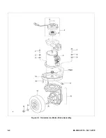
7-1. Drive Wheel.
1.
or 12,
) and disconnect the batteries.
2.
Remove the compartment covers as described in
paragraph
3.
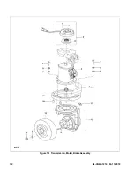
Loosen but do not remove the five nuts (15,
4.
Jack up the truck so the drive wheel is off the
ground; then securely block the truck to prevent
movement.
5.
Remove the five nuts (15), five washers (14) and
drive wheel (13) from the transmission (12).
6.
Install new drive wheel in reverse order of
removal.
7.
Install the compartment covers as described in
paragraph
8.
Reconnect the batteries and turn on the keyswitch
(12,
or 12,
7-2. Transmission.
1.
Remove the drive wheel (13) as described in
paragraph
2.
Remove the brake (2,
) as described in
paragraph
3.
Remove the steering arm as described in para-
graph
4.
Note routing of cables to ensure proper installa-
tion.
5.
Tag the cables connected to the drive motor; then
disconnect these cables from the drive motor.
6.
) and three
lock washers (27) to free brake plate (17) from
motor (3,
7.
Support the transmission (12,
) and
remove the six screws (7), six lock washers (8)
and six flat washers (9).
8.
Slowly lower the transmission out the bottom of
the frame.
9.
Install new transmission by reversing the steps
above.
7-3. Load Wheel.
7-3.1. Removal
1.
or 12,
) and disconnect the batteries.
2.
Block the drive wheel to prevent the truck from
rolling.
3.
Jack up the truck to raise the load wheel off the
floor. Securely block the truck in the raised posi-
tion.
4.
Remove three screws (1,
(2).
5.
Remove two screws (3), two lock washers (4), two
flat washers (5) and retainer (6).
6.
Remove load wheel (7).
7.
Remove bearings (13) from load wheel (7).
NOTE:
Inspect the load wheel assembly. If the load
wheel is worn within 1/8" of the metal sleeve,
or is cracked or damaged, replace the entire
load wheel and bearing assembly. Big Lift
LLC recommends that both load wheel
assemblies be replaced at the same time.
This ensures level and safe operation of the
lift truck.
7-3.2. Load Wheel Installation
1.
Install bearings (13,
) in load wheel (7).
2.
Position load wheel (7) on spindle.
3.
Remove retainer (6) and secure with two screws
(3), two lock washers (4) and two flat washers (5).
4.
Install cover (2) and secure with three screws (1).
5.
Remove blocking from under the truck and lower
to the ground.
6.
Reconnect the batteries and turn on the keyswitch
(12,
or 12,
Summary of Contents for CB22
Page 9: ...BL CB22 1214 04 11 2019 2 3 Figure 2 2 Sample of Operator Check List R6479 ...
Page 12: ...2 6 BL CB22 1214 04 11 2019 NOTES ...
Page 18: ...3 6 BL CB22 1214 04 11 2019 NOTES ...
Page 34: ...4 16 BL CB22 1214 04 11 2019 NOTES ...
Page 39: ...BL CB22 1214 04 11 2019 5 5 Figure 5 4 Cap Assembly R6878A ...
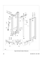
Page 42: ...6 2 BL CB22 1214 04 11 2019 Figure 6 1 Transmission Motor Brake Assembly R6879A ...
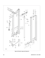
Page 44: ...7 2 BL CB22 1214 04 11 2019 Figure 7 1 Transmission Motor Brake Assembly R6879A ...
Page 45: ...BL CB22 1214 04 11 2019 7 3 Figure 7 2 Load Wheels R6882A ...
Page 46: ...7 4 BL CB22 1214 04 11 2019 NOTES ...
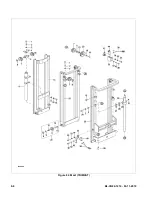
Page 48: ...8 2 BL CB22 1214 04 11 2019 Figure 8 2 Elevation System Telescopic R6883 ...
Page 50: ...8 4 BL CB22 1214 04 11 2019 Figure 8 3 Mast TRIMAST R6884A ...
Page 52: ...8 6 BL CB22 1214 04 11 2019 NOTES ...
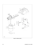
Page 54: ...9 2 BL CB22 1214 04 11 2019 Figure 9 1 Hydraulic System R8009 ...
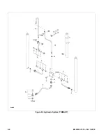
Page 56: ...9 4 BL CB22 1214 04 11 2019 Figure 9 3 Hydraulic System TRIMAST R6888A ...
Page 58: ...9 6 BL CB22 1214 04 11 2019 Figure 9 4 Elevation System Telescopic R6883A ...
Page 59: ...BL CB22 1214 04 11 2019 9 7 Figure 9 5 Lift Cylinder Telescopic R6889A ...
Page 61: ...BL CB22 1214 04 11 2019 9 9 Figure 9 6 Elevation System TRIMAST R6884A ...
Page 62: ...9 10 BL CB22 1214 04 11 2019 Figure 9 7 Free Lift Cylinder TRIMAST R6890A ...
Page 64: ...9 12 BL CB22 1214 04 11 2019 Figure 9 8 Secondary Lift Cylinder TRIMAST R6891 ...
Page 67: ...BL CB22 1214 04 11 2019 9 15 Figure 9 10 Tilt Cylinder R6893 ...
Page 68: ...9 16 BL CB22 1214 04 11 2019 NOTES ...
Page 72: ...10 4 BL CB22 1214 04 11 2019 Figure 10 3 Electrical Panel R6478 R6895A ...
Page 74: ...10 6 BL CB22 1214 04 11 2019 Figure 10 4 Transmission Motor Brake Assembly R6879A ...
Page 75: ...BL CB22 1214 04 11 2019 11 1 SECTION 11 OPTIONAL EQUIPMENT ...
Page 76: ...11 2 BL CB22 1214 04 11 2019 NOTES ...
Page 78: ...12 2 BL CB22 1214 04 11 2019 Figure 12 1 Steering System R6876A ...
Page 90: ...12 14 BL CB22 1214 04 11 2019 Figure 12 7 Transmission Motor Brake Assembly R6879A ...
Page 94: ...12 18 BL CB22 1214 04 11 2019 Figure 12 9 Transmission Used from Serial 327121134 DE_0050 ...
Page 96: ...12 20 BL CB22 1214 04 11 2019 Figure 12 10 Compartment R6880 ...
Page 98: ...12 22 BL CB22 1214 04 11 2019 Figure 12 11 Frame R6881 ...
Page 100: ...12 24 BL CB22 1214 04 11 2019 Figure 12 12 Load Wheels R6882A ...
Page 102: ...12 26 BL CB22 1214 04 11 2019 Figure 12 13 Elevation System Telescopic ...
Page 104: ...12 28 BL CB22 1214 04 11 2019 Figure 12 14 Elevation System Telescopic Continued R6883A ...
Page 106: ...12 30 BL CB22 1214 04 11 2019 Figure 12 15 Elevation System Three Stage R6884A ...
Page 108: ...12 32 BL CB22 1214 04 11 2019 Figure 12 16 Elevation System Three Stage Continued R6884A ...
Page 110: ...12 34 BL CB22 1214 04 11 2019 Figure 12 17 Lift Carriage Two Stage R6815A ...
Page 112: ...12 36 BL CB22 1214 04 11 2019 Figure 12 18 Lift Carriage Three Stage R8008 ...
Page 114: ...12 38 BL CB22 1214 04 11 2019 Figure 12 19 Chain Assembly R6818 ...
Page 122: ...12 46 BL CB22 1214 04 11 2019 Figure 12 23 Pump Motor Used from serial number 324200459 R8217 ...
Page 124: ...12 48 BL CB22 1214 04 11 2019 Figure 12 24 Hydraulic System Telescopic R6887A ...
Page 130: ...12 54 BL CB22 1214 04 11 2019 Figure 12 27 Tilt Cylinder Mounting R6892 ...
Page 132: ...12 56 BL CB22 1214 04 11 2019 Figure 12 28 Lift Cylinder Telescopic R6889A ...
Page 134: ...12 58 BL CB22 1214 04 11 2019 Figure 12 29 Free Lift Cylinder Three Stage R6890 ...
Page 140: ...12 64 BL CB22 1214 04 11 2019 Figure 12 32 Tilt Cylinder Used up to Serial S2118062 R6893A ...
Page 142: ...12 66 BL CB22 1214 04 11 2019 Figure 12 33 Tilt Cylinder Used from Serial S2118063 R8012 ...
Page 146: ...12 70 BL CB22 1214 04 11 2019 Figure 12 35 Electrical System Used from Serial S2320149 R8013 ...
Page 148: ...12 72 BL CB22 1214 04 11 2019 Figure 12 36 Electrical Panel Used up to Serial S2320148 R6895A ...
Page 150: ...12 74 BL CB22 1214 04 11 2019 Figure 12 37 Electrical Panel Used from Serial S2320149 R8014 ...
Page 152: ...12 76 BL CB22 1214 04 11 2019 Figure 12 38 Drive Motor R8015 ...
Page 154: ...12 78 BL CB22 1214 04 11 2019 Figure 12 39 Wiring Harness Used up to Serial S2320148 R6896A ...
Page 156: ...12 80 BL CB22 1214 04 11 2019 Figure 12 40 Wiring Harness Used from Serial S2320149 R8016 ...
Page 158: ...12 82 BL CB22 1214 04 11 2019 Figure 12 41 Wiring Cables Used up to Serial S2320148 R6897A ...
Page 160: ...12 84 BL CB22 1214 04 11 2019 Figure 12 42 Wiring Cables Used from Serial S2320149 R8017 ...
Page 168: ...Big Lift LLC ...


