background image

Installation, Operation and Maintenance Manual 

MAN 707 Rev. 3

March 2022

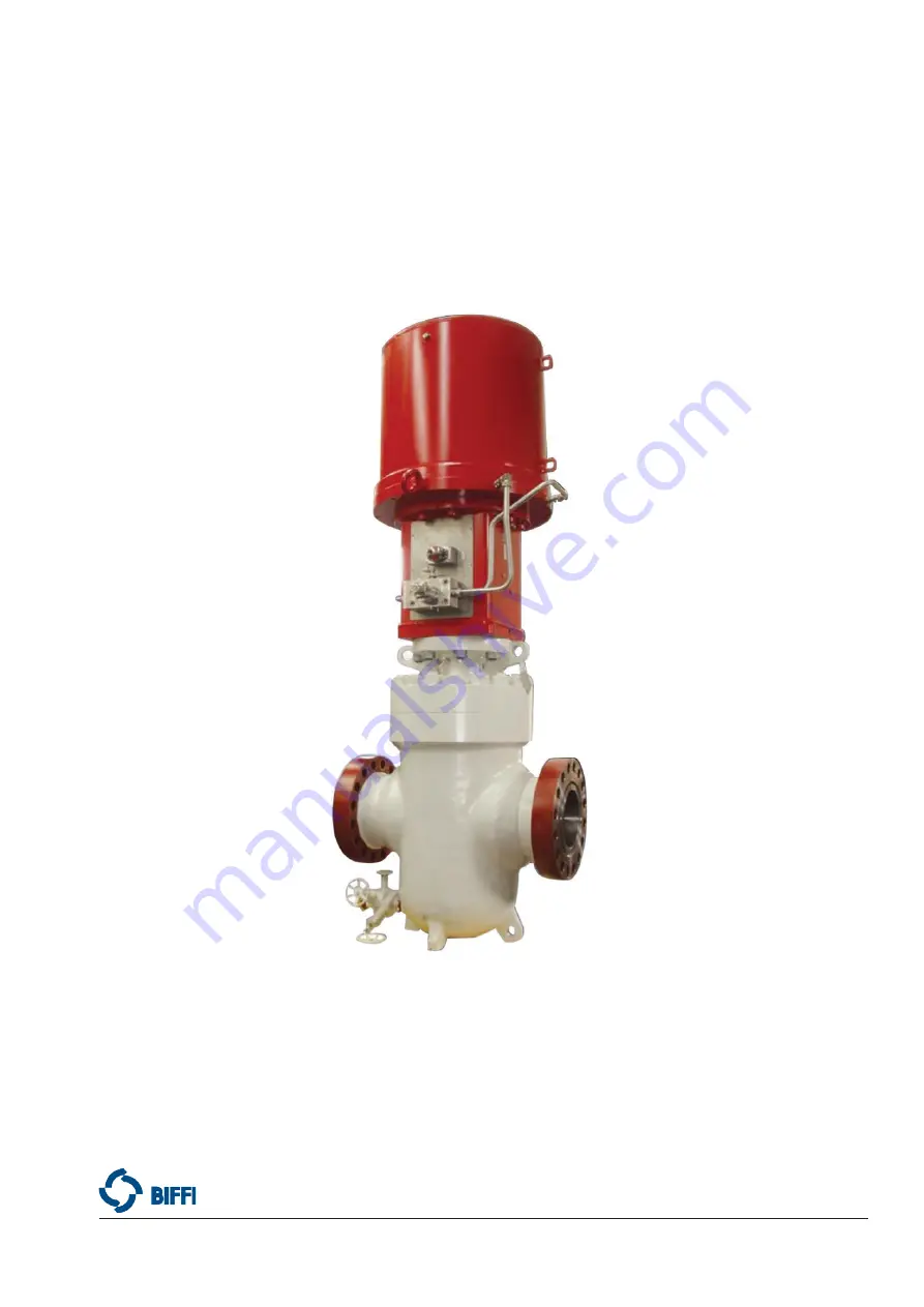
Biffi HLAS-C Compact Series

High Pressure Spring-Return Hydraulic Linear Actuator

Copyright © Biffi. The information in this document is subject to change without notice. Updated data sheets can be obtained from our website www.biffi.it or from your nearest Biffi Center: 


Biffi Italia s.r.l. - Strada Biffi 165, 29017 Fiorenzuola d'Arda (PC) –

 Italy PH: 

+39 0523 944 411 – [email protected]

Summary of Contents for HLAS-C 320 325 CL UP

Page 1: ...rn Hydraulic Linear Actuator Copyright Biffi The information in this document is subject to change without notice Updated data sheets can be obtained from our website www biffi it or from your nearest...

Page 2: ...Rev Date Description Prepared Checked Approved 3 March 2022 General update Migration to new template 2 May 2018 Updated applicable regulation chapter 1 1 1 Ermanni Orefici Vigliano 1 April 2016 Updat...

Page 3: ...rocedure 6 2 5 Hydraulic Connections 10 2 6 Electrical Connections If Any 10 2 7 Commissioning 11 Section 3 Operation and Use 3 1 Operation Description 12 3 2 Residual Risks 13 3 3 Operations 13 3 3 1...

Page 4: ...Contents Table of Contents Section 6 Troubleshooting 6 1 Failure or Breakdown Research 30 Section 7 Layouts 7 1 Spare Parts Order 31 7 2 Parts List for Maintenance and Replacing Procedure 32 Section...

Page 5: ...r damage or accidents due to the use of the latter The information contained is of exclusive reserved ownership of Biffi Italia s r l and may be modified without prior notice All rights reserved 1 1 2...

Page 6: ...g and in closing position by the actuator hydraulic cylinder in one direction and by the spring unit in the other direction The output thrust of spring unit can be downward or upward according to valv...

Page 7: ...Mineral oil synthetic or fire resistant fluids Operating temperature Standard from 30 C to 100 C Optional from 60 C to 100 C Design pressure range for cylinder 105 352 barg 1500 5000 psig Max oil ope...

Page 8: ...ctuator is received already assembled with the valve its settings have already been made at the factory If the actuator is delivered separately from the valve it is necessary to check and if required...

Page 9: ...manual handpump when it was necessary put the tank of MHP in horizontal position to avoid leakage on oil level stick substitute this with a blind plug during the transport a specific warning label fo...

Page 10: ...y The adapter pedestal in fabricated carbon steel is specifically designed for adaptation to any type of valve with provision for local indicator limit switches and other accessories on request Lift t...

Page 11: ...actuator and lift it To make the assembly easier the valve stem has to be in perfect vertical position 3 Screw the actuator coupling joint onto the valve by rotating the actuator or screw down the val...

Page 12: ...llation B To assemble the actuator onto the valve by bracket with shell joint perform the following operations Figure 6 Pedestal with shell coupling joint Item Description 1 Stud bolt 2 Nut 3 Nut 4 Sc...

Page 13: ...from the actuator pedestal 5 Assemble the actuator onto the valve and arrange it in its correct vertical position proper to connection between valve stem and actuator cylinder rod 6 Screw the valve s...

Page 14: ...hem plenty of the supply fluid used in the system Mold and fasten the connection pipes so that no irregular strains at entries or loosening of threaded connections occur Make the connections according...

Page 15: ...re switches etc are compatible with those reported on the identification plate of the actuator Figure 1 Check that the setting of the components of the actuator control unit pressure regulator pressur...

Page 16: ...tarts the linear motion of the piston and the consequent motion of the valve stem that is coupled The spring action operates the valve stem in the opposite direction fail safe position Figure 7 For lo...

Page 17: ...to applicable control schematic in supplied documentation The HLAS C actuators can have an emergency manual override in addition to the local and or remote control system which controls the oil suppl...

Page 18: ...mote control to close De energize at least one of the solenoid valves 424A and 424B The closing time is adjustable by the flow regulator 530B 1 Single acting spring return hydraulic linear actuator 41...

Page 19: ...sition fully open and fully closed except when this is required by the valve operation The setting of the open closed valve position upward position is performed by adjusting the travel stop screw int...

Page 20: ...of protection flange 2 until reaching the stop setting screw 3 If the actuator angular stroke is stopped before reaching the upward position fully open or closed unscrew the stop setting screw by turn...

Page 21: ...n rings see Section 7 2 Figure 25 item 10 To increase the linear stroke unscrew the regulation rings from threaded surface of stem valve joint see Section 7 2 Figure 25 item 8 To decrease the linear s...

Page 22: ...lease refer to the relative wiring diagram and follow these steps Unscrew the fastening screws of the cover Figure 15 Remove the cover paying attention not to deteriorate the gasket and the cylindrica...

Page 23: ...gure 17 does not signal the proper position of the valve but is turned by 90 Remove the roll pin placed on the position indicator index Turn the indicator until reaching its proper positioning Put the...

Page 24: ...nd Use Operation and Use Figure 18 Transmission device for non Biffi limit switch box Position indicator index pin Figure 17 Position indicator and pin for microswitches box NOTICE Refer for informati...

Page 25: ...of operating time by flow regulator valve Torque 30 Nm Torque 5 Nm Technical features Max adjusted flow L min 10 Max working pressure bar 250 Fluid viscosity range cSt 5 750 Fluid temperature range C...

Page 26: ...erational Tests and Inspections Operational Tests and Inspections Section 4 Operational Tests and Inspections NOTICE To ensure the guaranteed SIL grade according to IEC 61508 the functionality of actu...

Page 27: ...leakages If necessary tighten the nuts of the pipe fittings Check oil level into the hydraulic manual handpump if present refer to technical documentation furnished for this component Check that the a...

Page 28: ...iscosity at 40 C 491 cST Viscosity at 40 C 14 1 cST Viscosity at 100 C 5 30 cST Viscosity index ISO 2909 200 Flash point 105 C Pour point 60 C Specific weight 0 87 kg dm or equivalent Low temperature...

Page 29: ...de 001A0065 Infosafe No ACISO GB eng C Table 6 5 2 Extraordinary Maintenance If there are leaks in the hydraulic cylinder or a malfunction in the mechanical components or in case of scheduled preventi...

Page 30: ...14 15 Figure 23 Section 7 2 2 Lift the spring module with hook for chain as explained in Section 2 2 3 Unscrew the screws see item 22 Figure 25 Section 7 2 to disassemble the pedestal from the base of...

Page 31: ...ber O ring by bending it take care that the bending radius is as large as possible to avoid damaging the seal Then enlarge the seal ring with your fingers so as to restore its round shape Pay attentio...

Page 32: ...aded end and tighten 3 Carefully clean the inside of the tube 11 and check that the entire surface particularly that of the bevels is not damaged Lubricate the tube internal surface and the bevels at...

Page 33: ...ized staff Before starting the disassembly a large area should be created around the actuator so as to allow any kind of movement without problems of further risks created by worksite Separate the par...

Page 34: ...ibration of flow regulator valves Restore Section 3 6 Wear of the valve Replace Actuator too fast High supply pressure Restore Section 1 4 Wrong calibration of flow regulator valves Restore Section 3...

Page 35: ...fi order confirmation concerning all the supply and serial number of the actuator Section 1 2 for any specific spare part for a specific actuator model Please send every spare parts request to Biffi I...

Page 36: ...32 March 2022 Installation Operation and Maintenance Manual MAN 707 Rev 3 Layouts Section 7 Layouts 7 2 Parts List for Maintenance and Replacing Procedure Figure 22 Hydraulic cylinder D A B C A B C D...

Page 37: ...2 6 Screw Stainless steel 13 1 O ring NBR rubber 14 1 O ring NBR rubber 15 1 O ring NBR rubber 16 1 O ring NBR rubber 17 1 O ring NBR rubber 18 1 Bushing Steel Bronze Teflon 19 1 Bushing Steel Bronze...

Page 38: ...End flange Carbon steel 4 1 Upper spring flange Carbon steel 5 1 Lower spring flange Carbon steel 6 3 Half ring Alloy steel 7 1 Spring container Carbon steel 8 1 Spring Spring steel 9 1 Spring Spring...

Page 39: ...screw Item Qty Description Material 1 1 Gasket SBR cellulose fillers 2 1 Stop setting screw flange Carbon steel 3 1 Stop setting screw Stainless steel 4 1 Pin Nylon 5 8 Screw Stainless steel 6 1 O ri...

Page 40: ...ss steel 6 2 Spacer Stainless steel 7 1 Shell joint Stainless steel 8 1 Stem valve joint Stainless steel 9 1 Stem actuator joint Stainless steel 10 2 Regulation ring Stainless steel 11 1 Spacer valve...

Page 41: ...1 Limit switches box gasket NBR rubber 4 1 Setting plate Stainless steel 5 1 Limit switches box adaptor plate Stainless steel 6 1 Closing plate gasket NBR rubber 7 1 Screw Stainless steel 8 8 Screw St...

Page 42: ...for Maintenance Operations Date Report for Maintenance Operations Last maintenance operation date in factory on delivery exec by exec by exec by Next maintenance operation date exec by exec by exec by...

Page 43: ...Notes Installation Operation and Maintenance Manual MAN 707 Rev 3 March 2022 This page is intentionally left blank...

Page 44: ...he products or services described herein or their use or applicability All sales are governed by our terms and conditions which are available on request We reserve the right to modify or improve the d...

Reviews: