background image

The flue length is measur

ed from the

centreline of the appliance flue outlet to the
inside of the external wall-sealing ring. In
most cases it will be possible to achieve the
required flue length without cutting the ducts,
however where necessary the plain ends of
the extension ducts may be cut. Never cut the
swaged end, and always ensure that the cut
is square and free of burrs or debris.

NOTE IT IS ESSENTIAL THAT THE TERMINAL
IS FITTED THE CORRECT WAY UP See flue
kit Instructions (i.e. rain shield at the top).

4.7.1

Installing the air/flue duct from inside
the room

a)

Push the terminal through the wall liner taking
care to ensure that the terminal is the correct
way round and the external wall-sealing ring
does not become dislodged.

b) Assemble the flue system extension ducts as

necessary, referring to Figure 15.

c) Pull the flue system towards the appliance to

seat the external sealing ring against the
outside wall, ensuring that the duct joints are
not disturbed.

d) Use the internal sealing ring to make good the

internal hole, and check that the terminal is
correctly located on the outside wall (Where
possible this should be visually checked from
outside the building.) Figure 15 shows a view
of the flue system, correctly installed.

INST

ALLA

TION

19

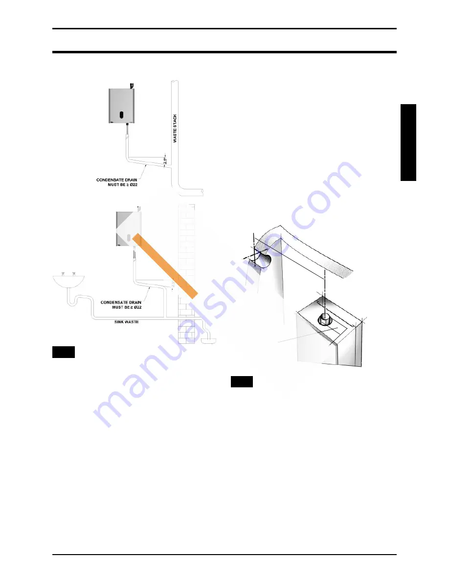
Condensate Connections

Fig. 13.

4.7

Air/Flue Duct Installation

For corr

ect flue installation please refer to the

installation instructions that are provided with
the individual flue kit as described in sections
2.5 - 2.6.

a) Measure the required flue length as shown in

Figure 14. Refer to section 2.5 to determine
whether any extension kits are required.
Installations using only the standard ducts or
standard ducts with straight extensions are
described in this section. Installation
instructions for all other flue systems are
included in the various flue kits.

b) Ensure that all (inner and outer tube) sealing

rings are provided and assemble the air/flue
ducts as shown in the flue instructions.

c) Construct the correct flue length by building

the flue out from the appliance. 

Ensur

e that

the flue and air seals are correctly fitted
before assembly and that each section is
fully engaged.

Fig. 14.

Measuring the exact flue length

TOTAL FLUE LENGTH
FROM FLUE OUTLET
CENTRE TO OUTSIDE
WALL FACE:
= LENGTH  L

W

ALL

OUTLET

INTERNAL
Dia. 60mm

L

Summary of Contents for RIVA OV M110.18SM/OV

Page 1: ... Installation instructions RIVA OV Models G C Appl No M110 18SM OV 41 260 21 M110 30SM OV 41 260 22 U n i t 3 A T h o r n t o n R o a d I n d E s t a t e O f f H o c k n e y R o a d B r a d f o r d B D 8 9 H Q 0 1 2 7 4 4 8 8 3 8 8 w w w h e a t i n g s p a r e s 2 4 7 c o m ...

Page 2: ...ted with all the safety and control devices required by the current Regulations Ensure that the installer has connected the condensate outlet to a suitable drain pipe On detecting the smell of gas don t operate any electrical switches the telephone or any device that may produce sparks open the windows and doors at once to create a draught of air which will purge the area shut off the gas cocks ge...

Page 3: ...present high risk follow good hygiene practices and wash hands before touching eyes consuming food drinking or using the toilet First aid medical attention must be sought following eye contact or prolonged reddening of the skin Appliance category l2H Gas G20 20 mbar Country of destination United Kingdom GB Ireland IE This appliance conforms with the EEC directive 90 396 and consequently it has the...

Page 4: ...ter a time you must also indicate which days that you want the boiler to follow the timed settings Some products incorporate an anti cyclonic time delay It is normal when first switching the boiler on for the boiler to operate on heating for a few seconds then switch off After 3 4 minutes has elapsed the boiler will then re ignite and operate perfectly normally If you are in any doubts as to the i...

Page 5: ...rols 0 4 Appliance Installation 0 4 1 Unpacking The Appliance 0 4 2 Preparing The Wall 0 4 3 Mounting The Appliance 0 4 4 Central Heating Service Connections 0 4 5 Gas Connection 0 4 6 Condensate Connection 0 4 7 Air Flue Duct Installation 0 4 8 Electrical Connections 0 5 Commissioning 0 5 1 Filling the Water System 0 5 2 Commissioning the Appliance 0 5 3 Final Checks 0 5 4 Lockout Reset Indicatio...

Page 6: ...th and up to the maximum dimensions stated in these instructions A vertical concentric outlet kit is also available for installations where an outside wall is not accessible or where it is desired to fit the duct through the roof Installation using the horizontal or vertical duct is described in the main text of these instructions and additional information is provided in the flue kit for the vert...

Page 7: ...wn or suspected that a fault exists on the appliance it MUST NOT be used until the fault has been rectified by a competent person 1 2 2 Electrical Supply This appliance must be earthed Supply 230V 50Hz fused at 3A This method of connection to the mains supply must facilitate complete isolation of the appliance Either a 3A fused three pin plug and un switched shuttered socket outlet or a 3A fused d...

Page 8: ...heating system water reaches temperatures below 5ºC If either the gas or electricity services is to be isolated during a period when frost is likely the water circuits must be drained 1 4 4 Boiler overheat Thermostat The appliance is fitted with two thermistors located on the flow and return pipes In the event of overheating the boiler will shut down and the display will show 1 Allow the boiler to...

Page 9: ... NOTE RPM SIGNAL FAN SPEED SIGNAL IN REVOLUTIONS PER MINUTE BCC BOILER CHIP CARD A SMALL MICROCHIP THAT PUSH FITS ONTO THE CONTROL PCB AND ALTERS OPERATING PARAMETERS SEE SECTION 7 FIG 31 FAULT CODES 1 4 CAN BE RESET BY FOLLOWING THE PROCEDURE IN SECTION 1 4 5 HOWEVER IF ANY OTHER FAULT CODE IS SHOWING PLEASE CONTACT YOUR INSTALLER OR BIASI UK LTD TECHNICAL HELPLINE 0121 506 1350 1 7 Warning If a ...

Page 10: ...ecifications Seasonal Efficiency 90 4 Seasonal Efficiency SEDBUK Band A NOx Classification Class 5 Min Cen Heating Press Bar 0 1 1m H20 Max Cen Heating Press Bar 3 0 Max Cen Heat Flow Temp ºC 80 Min Cen Heat Flow Temp ºC 30 Central Heating Output Non Condensing 80 60ºC Max kW 18 0 BTU h 61400 Min kW 5 9 BTU h 20100 Condensing 50 30ºC Max kW 19 3 BTU h 65900 Heat Input Max Rate Net kW 18 4 BTU h 62...

Page 11: ...Water Capacity l 1 3 Electrical Supply 230V 50Hz Fuse 3A Internal Fuse T4H 4A 250V Max Power Consumption W 30 IP Rating IP 20 Flue Gas Temp Nat Gas 80 60 ºC 74 Flue Gas Temp Nat Gas 50 30 ºC 43 CO2 Value Max Rate 9 2 0 3 Case on Nat Gas 9 0 0 2 Case off CO2 Value Min Rate 8 4 0 1 Nat Gas ref only CO Value Max Rate 0 01 0 005 Nat Gas Flue Products mass g s 8 3 flow rate Nat Gas Gas Valve Offset min...

Page 12: ...o discharge horizontally it is not designed to enable termination in the vertical plane Vertical kit with 90º elbow Fig 3 Co axial 60 100mm Supplied with a straight flanged adapter a co axial elbow and a co axial pipe with terminal this kit allows for a vertical rise of 0 5 m from the boiler In all circumstances the flue terminal must discharge horizontally and the equivalent flue length must not ...

Page 13: ...th of the room sealed flue system are Horizontal flue terminal all orientations maximum 10 m 393 in Horizontal flue terminal rear exit minimum 250 mm 10 in Vertical flue terminal maximum 12 m 472 in Vertical flue terminal minimum 600 mm 23 5 in The equivalent flue length must not exceed the maximum values stated b The standard terminal must always be fitted horizontally horizontal ducts must have ...

Page 14: ...0 2 7 Appliance Hydraulic Circuit Fig 4 U n i t 3 A T h o r n t o n R o a d I n d E s t a t e O f f H o c k n e y R o a d B r a d f o r d B D 8 9 H Q 0 1 2 7 4 4 8 8 3 8 8 w w w h e a t i n g s p a r e s 2 4 7 c o m ...

Page 15: ...ition MUST allow for a suitable flue system and terminal position The appliance must be installed on a flat vertical wall which is capable of supporting the weight of the appliance and any ancillary equipment c If the appliance is to be fitted in a timber framed building it should be fitted in accordance with the British Gas publication Guide for Gas Installations In Timber Frame Housing Institute...

Page 16: ...e aggregate maximum rated input shall be used to determine the air vent free area BS 5440 2 Table 2 d Where an open flued system is used and the flue duct air inlet is within a compartment then high and low level air vents are necessary in the compartment the size of the vents should be calculated in accordance with BS 5440 2 Table 2 The minimum acceptable spacing from the terminal to obstructions...

Page 17: ...ors and windows also extinguish any cigarettes pipes and any other naked lights g The complete installation must be tested for gas tightness 3 7 Central Heating System a The appliances are designed for open vented central heating water systems but may be fitted to a sealed central heating system provided the necessary components such as expansion vessel and pressure safety relief valve are fitted ...

Page 18: ...tive positions of the pump cold feed and open vent are as shown in figure 9 3 14 Domestic Hot Water Cylinder SINGLE FEED INDIRECT CYLINDERS ARE NOT SUITABLE The domestic hot water cylinder must be of the double feed fully indirect coil type 3 15 Sealed Water Systems The installation must comply with the appropriate requirements of the current issue of BS4814 BS5449 BS6759 BS6798 and BS7074 Part 1 ...

Page 19: ...em at low level must be made see figure 7 There must be no permanent connection to the mains water supply even through a non return valve CONTROLS As a minimum it is recommended that a room thermostat be installed to control the appliance Thermostatic radiator valves may be fitted to the system however they must not be fitted in the room where the room thermostat is fitted There must be at least o...

Page 20: ...EARTHED Failure to provide a satisfactory earth connection will result in appliance malfunction The RIVA OV appliances may be used with any certified programmer room thermostat as described in section 4 For further information contact BIASI UK Ltd Technical helpline 0121 506 1350 3 22 External Controls d The method of connection to the mains supply must facilitate complete electrical isolation of ...

Page 21: ...eeds to be taken into account Refer to Figure 9 Remove the paper template d Cut the hole in the wall for the air flue duct preferably with a core boring tool The hole must be horizontal and not be less than 100 mm in diameter If the hole is not accessible from outside its minimum diameter must be sufficient to allow insertion of a wall liner 130 mm 5in which must be sealed in position with mortar ...

Page 22: ...a minimum of 22 mm diameter OD copper pipe be used to within 1000 mm of the gas service cock 4 6 Condensate Connection Refer to Figure 12 Connect preferably a 22 mm plastic push fit or adhesive overflow pipe to the condensate outlet It should be piped to drain preferably within the building maintaining a continuous 2 fall away from the appliance Note The internal trap has a seal of 150 mm therefor...

Page 23: ...d be visually checked from outside the building Figure 15 shows a view of the flue system correctly installed INSTALLATION 19 Condensate Connections Fig 13 4 7 Air Flue Duct Installation For correct flue installation please refer to the installation instructions that are provided with the individual flue kit as described in sections 2 5 2 6 a Measure the required flue length as shown in Figure 14 ...

Page 24: ...e wall from outside the building 4 8 Electrical Connections Connect the electricity supply and external controls using suitable mains cable as follows Wire the cable s into the appropriate connections in the electrical plug provided referring to Figure 16 Live supply to L1 Neutral and Earth as indicated Check that L1 and L3 are linked To provide correct cable retention fit the piece of tubing supp...

Page 25: ...grammer Fig 18 Fully Pumped Y Plan Fig 19 Upp15 50 Pump Plan Wiring Centre Connections U n i t 3 A T h o r n t o n R o a d I n d E s t a t e O f f H o c k n e y R o a d B r a d f o r d B D 8 9 H Q 0 1 2 7 4 4 8 8 3 8 8 w w w h e a t i n g s p a r e s 2 4 7 c o m ...

Page 26: ...struction with the system hot It is recommended that the system be cleaned with a recognised system cleaner such as Fernox or Sentinel Prior to lighting the appliance to check the gas rates the central heating system should be checked for circulation by operating the appliance with the gas turned off this is to ensure that no air locks occur The appliance may go into ignition lockout and require r...

Page 27: ...nder instructions If the boiler is connected to a hot water cylinder the CH temperature has to be set to high 5 4 Lockout Reset Indication In the event of failure during an ignition sequence 5 attempts the LED displays fault code 3 In order to reset the boiler turn the CH Temperature Control anticlockwise to STANDBY position and then back to ON within two seconds Fig 23 Inlet Pressure Test Point 5...

Page 28: ...o prevent damage to the system and to the building in the event of the system remaining inoperative during frost conditions e Explain the function of the CH Temperature Control knob and how to reset the appliance Emphasise that if cutouts persists the appliance should be turned off and the installer or service engineer consulted f Stress the importance of an annual service by a registered heating ...

Page 29: ...tion ISOLATE the mains electrical supply and TURN OFF the gas supply at the main service cock 6 2 Gas Control Valve Fan Burner Assembly Refer to Figures 25 26 27 and 28 a Remove the hinges and take off the hinged front panel b Remove the decorative front cover 4 screws c Remove the sealed chamber door 6 screws d Disconnect the igniter plug earth lead and detection plug from the igniter and detecti...

Page 30: ...chamber for debris If necessary clean the inside of the tubes with a soft brush Do not brush the insulation at the rear check the integrity of the combustion chamber insulation panels if damaged they will require replacement 6 6 Condensate Drain The condensate Drain has a removable cap Figure 30 which allows the removal of debris that may be caught within it Place a bowl under the cap to catch the...

Page 31: ...ess than 0 75 bar recharge vessel with an air pump 6 8 Re assembly Re commissioning a Re assemble all components in reverse order b Check that all joints and seals are correctly fitted c Turn on the gas and electricity supply and light the appliance as described in section 5 2 d Re perform a combustion check as described in section 6 1 e Check the operation of the appliance in CH mode f Remove the...

Page 32: ...iring Diagrams Fig 31 Functional Flow Wiring Diagram U n i t 3 A T h o r n t o n R o a d I n d E s t a t e O f f H o c k n e y R o a d B r a d f o r d B D 8 9 H Q 0 1 2 7 4 4 8 8 3 8 8 w w w h e a t i n g s p a r e s 2 4 7 c o m ...

Page 33: ... refer to the Diagnostics Chart 8 4 Central Heating Fault Finding Upon a demand for Central Heating closure of the time switch and room thermostat where fitted the controls should carry out a set of start up checks followed by an ignition sequence Refer to Section 5 2 If the control has powered up correctly but does not respond to a CH demand Remove plug cover and check voltage between L3 orange a...

Page 34: ...ame Flue gas temperature greater than 95 C Check gas supply Check gas service cock Check gas valve and lead Check detection electrode lead Check gas supply Check gas valve and lead Check PCB X2A X2B connectors Check spark generator spark electrode Check mains earth lead continuity Check flue sensor Check flue system Check no air is in heat exchanger CH system Check external pump Check PCB PCB conn...

Page 35: ...rs Check wires to sensors not crossed Check mains voltage Check PCB connectors No light indication Defective power supply Check power supply Check PCB X1B connector Check PCB fuse No flame No demand Faulty connector Check PCB X1A connector Check programmer room thermostat Activate BCC No flame New BCC Turn CH control knob to reset twice to activate NOTE RPM SIGNAL FAN SPEED SIGNAL IN REVOLUTIONS P...

Page 36: ...8 OV1066101 7b Heat Exchanger OV 30 OV1066102 8 Water Temperature Sensor OV1066103 9 Flue Sensor OV1011101 10 Manual Bleed Valve OV1066104 11 Control PCB OV1077100 12 User Interface OV1077101 13 Heat Exchanger Seal Kit OV1066105 KEY G C PART NO DESCRIPTION MAKERS PT NO Fig 33 1 9 12 6 3 4 2 5 7 8 10 11 U n i t 3 A T h o r n t o n R o a d I n d E s t a t e O f f H o c k n e y R o a d B r a d f o r ...

Page 37: ...EEN FITTED YES NO WHAT TYPE OF SCALE REDUCER HAS BEEN FITTED FOR CONDENSING BOILERS ONLY CONFIRM THE FOLLOWING THE CONDENSATE DRAIN HAS BEEN INSTALLED IN ACCORDANCE WITH THE MANUFACTURERS INSTRUCTIONS YES FOR ALL INSTALLATIONS CONFIRM THE FOLLOWING THE HEATING AND HOT WATER SYSTEM COMPLIES WITH CURRENT BUILDING REGULATIONS THE APPLIANCE AND ASSOCIATED EQUIPMENT HAS BEEN INSTALLED AND COMMISSIONED ...

Page 38: ...NY NAME TEL No CORGI ID SERIAL No COMMENTS SIGNATURE SERVICE 4 DATE ENGINEER NAME COMPANY NAME TEL No CORGI ID SERIAL No COMMENTS SIGNATURE SERVICE 5 DATE ENGINEER NAME COMPANY NAME TEL No CORGI ID SERIAL No COMMENTS SIGNATURE SERVICE 6 DATE ENGINEER NAME COMPANY NAME TEL No CORGI ID SERIAL No COMMENTS SIGNATURE SERVICE 7 DATE ENGINEER NAME COMPANY NAME TEL No CORGI ID SERIAL No COMMENTS SIGNATURE...

Page 39: ...Y NAME TEL No CORGI ID SERIAL No COMMENTS SIGNATURE SERVICE 14 DATE ENGINEER NAME COMPANY NAME TEL No CORGI ID SERIAL No COMMENTS SIGNATURE SERVICE 15 DATE ENGINEER NAME COMPANY NAME TEL No CORGI ID SERIAL No COMMENTS SIGNATURE SERVICE 16 DATE ENGINEER NAME COMPANY NAME TEL No CORGI ID SERIAL No COMMENTS SIGNATURE SERVICE 17 DATE ENGINEER NAME COMPANY NAME TEL No CORGI ID SERIAL No COMMENTS SIGNAT...

Page 40: ...ury WV10 7BJ Technical Helpline 0121 506 1350 Web site www biasi co uk U n i t 3 A T h o r n t o n R o a d I n d E s t a t e O f f H o c k n e y R o a d B r a d f o r d B D 8 9 H Q 0 1 2 7 4 4 8 8 3 8 8 w w w h e a t i n g s p a r e s 2 4 7 c o m ...

Reviews: