


143
GR
CZ
HU
ES
IE
PT
1
- INSTALLER
BOILER
INSTALLATION
1.1 INSTALLATION
RECOMMENDATIONS.
The Maior Eolo boiler has been designed for wall
mounted installation; they must be used to heat
environments, to produce domestic hot water
and similar purposes. In the case of wall instal-
lation the wall surface must be smooth, without
any protrusions or recesses enabling access to the
rear part. They are NOT designed to be installed
on plinths or floors (Fig. 1-1).
By varying the type of installation the classifica-
tion of the boiler also varies, precisely:
-
Boiler type B
22
if installed without the 2 intake
caps and with the top cover kit.
-
Type C
boiler if installed using concentric pipes
or other types of pipes envisioned for the sealed
chamber boiler for intake of air and expulsion
of flue gas.
Only professionally qualified heating/plumbing
technicians are authorised to install Immergas
gas appliances. Installation must be carried out
according to the standards, current legislation
and in compliance with local technical regula-
tions and the required technical procedures. In-
stallation of the Maior Eolo boiler when powered
by LPG must comply with the rules regarding
gases with a greater density than air (remember,
as an example, that it is prohibited to install sy-
stems powered with the above-mentioned gas in
rooms where the floor is at a lower quota that the
average external country one). Before installing
the appliance, ensure that it is delivered in per-
fect condition; if in doubt, contact the supplier
immediately. Packing materials (staples, nails,
plastic bags, polystyrene foam, etc.) constitute
a hazard and must be kept out of the reach of
children. If the appliance is installed inside or
between cabinets, ensure sufficient space for
normal servicing; therefore it is advisable to
leave clearance of at least 3 cm between the boiler
casing and the vertical sides of the cabinet. Leave
adequate space above the boiler for possible water
and flue removal connections.
Keep all flammable objects away from the ap-
pliance (paper, rags, plastic, polystyrene, etc.).
Do not place household appliances underneath
the boiler as they could be damaged if the safety
valve intervenes (if not conveyed away by a
discharge funnel), or if there are leaks from the
connections; on the contrary, the manufacturer
cannot be held responsible for any damage cau-
sed to the household appliances.
In the event of malfunctions, faults or incorrect
operation, turn the appliance off immediately
and contact a qualified technician (e.g. the
Immergas After-Sales Assistance centre, which
has specifically trained staff and original spare
parts). Do not attempt to modify or repair the
appliance alone. Failure to comply with the above
implies personal responsibility and invalidates
the warranty.
• Installation regulations:
- this boiler can be installed outdoors in a
partially protected area. A partially protected
location is one in which the appliance is not
exposed to the direct action of the weather
(rain, snow, hail, etc..).
- Installation in places with a fire risk is
prohibited (for example: garages, box), gas
appliances and relative flue ducts, flue exhaust
pipes and combustion air intake pipes.
- Installation is also prohibited in places/en-
vironments that constitute common parts of
office condominiums such as stairs, cellars,
entrance halls, attics, lofts, escape routes,
etc. if they are not located inside technical
compartments under the responsibility of
each individual building and only accessible
to the user (technical compartments and the
appliances must be realised and installed in
compliance with fire prevention Standards).
Important:
Wall mounting of the boiler must
guarantee stable and efficient support for the
generator.
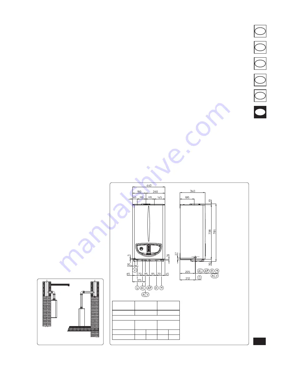
Fig. 1-1
1.2 MAIN DIMENSIONS.
The plugs (standard supply) are to be used only in
conjunction with the mounting brackets or fixing
template to fix the appliance to the wall;
they only
ensure adequate support if inserted correctly
(according to technical standards) in walls made
of solid or semi-hollow brick or block. In the
case of walls made from hollow brick or block,
partitions with limited static properties, or in any
case walls other than those indicated, a static test
must be carried out to ensure adequate support.
N.B.: the hex head screws supplied in the blister
pack are to be used exclusively to fix the relative
mounting bracket to the wall.
These boilers are used to heat water to below
boiling temperature in atmospheric pressure.
They must be attached to a heating system sui-
table for their capacity and voltage.
Height
(mm)
Width
(mm)
Depth
(mm)
781
440
340
CONNECTIONS
GAS
DOMESTIC
HOT WATER
SYSTEM
G
AC
AF
R
M
3/4”
1/2”
1/2”
3/4”
3/4”
Fig. 1-2
Key:
G - Gas supply
AC - Domestic hot water outlet
ACV - Solar valve kit DHW inlet (Optional)
AF - Domestic cold water inlet
R - System return
M - System flow
V - Electrical connection
N.B.: connection group (optional)
YES
NO
Summary of Contents for Maior Eolo 24 4E
Page 25: ...167 GR CZ HU ES IE PT Fig 3 5 4 4 5 6 6 d d c ...
Page 29: ......


