


Installation
26
1
2
L
N
3
To fused spur
isolation switch
Power supply
terminal block
External controls
terminal block
J
Fig. 6.17
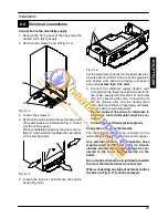
8 Connect the room thermostat between ter-
minals 1 and 3 as shown in Fig. 6.18 or
Fig. 6.19.
Power supply
terminal block
External controls
terminal block
T
Room thermostat
1
2
L
N
3
(230V rating)
Fig. 6.18
Power supply
terminal block
External controls
terminal block
T
Room thermostat
1
2
L
N
3
with delay resistor
(230V rating)
Fig. 6.19
9 Route the electrical supply flexible cord and
the external control flexible cord as illustrated
in Fig. 6.20.
Lock the flexible cords in place with the flexible
cord clamps
To the fused spur
To the external
control device
isolation switch
Fig. 6.20
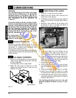
6.10
External frost protection
10 Connect the frost thermostat between ter-
minals 1 and 2 as shown in Fig. 6.21 or
Fig. 6.22
Do not connect live wires to terminals to
which the room thermostat must be con-
nected.
Power supply
terminal block
External controls
terminal block
T
Room thermostat
1
2
L
N
3
(230V rating)
T
Frost Thermostat
(230V rating)
Fig. 6.21
IN
S
TA
LLA
TI
O
N