


6
INSTALLATION
20
6.1
Warnings
The use of gas appliances is subject to
statutory control; it is essential to observe
the current regulations and laws in force
(see also chapter 5).
The appliance must discharge combustion
products directly outside or into a suitable ex-
haust duct designed for this purpose.
Combustion products must be discharged
using original flue kits only, since they are inte-
gral parts of the boiler.
For LPG, the appliance must also conform with
the requirements of the distributors and com-
ply with current Regulations and laws in force.
The safety relief valve and the condensate
drain must be connected to a suitable drain, or
discharge in a safe manner.
The electrical wiring must conform with current
Regulations, in particular:
---
the boiler
must
be earthed using the cor-
rect bonding clamp.
---
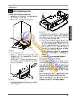
Adjacent to the boiler a fused spur isolation
switch must be installed which permits a
complete switching off in the conditions of
the overvoltage category III. Refer to sec-
tion 6.9 in this chapter for the electrical con-
nections.
In no circumstances will the manufacturer
be held responsible if the warnings and in-
structions contained in this manual have
not been complied with.
6.2
Precautions for installation
For the installation proceed as follows:
---
The boiler must be fixed to a strong wall.
---
The dimensions for the exhaust fume duct de-
tailed in section 6.7 and the correct procedures
for installing the duct, depicted in the instruc-
tion leaflet included with the flue kit, must be
complied with during installation.
---
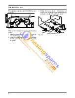
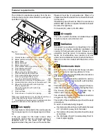
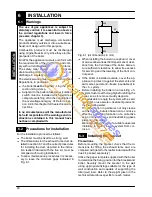
To allow maintenance procedures it is necess-
ary to leave the minimum gaps indicated in
Fig. 6.1.
25
50
250
200
Fig. 6.1 (all dimensions in mm)
---
When installing the boiler in a cupboard, cover
or alcove allow at least 50mm permanent clear-
ance from the front face of the boiler. Also en-
sure sufficient clearance to allow free access
for servicing and the lowering of the front con-
trol panel.
---
If the boiler is installed outside, cover the ap-
pliance to protect it against the elements and
add some special anti---freeze (neutralised) to
the c.h. system.
---
Before installing the boiler on an existing c.h.
system, flush it out thoroughly before fitting the
boiler, so as to remove muddy deposits.
---
It is advisable to equip the system with a sedi-
ment filter, or use a water---treatment product in
the circulating water.
The latter option in particular, not only cleans
out the system, but also has an anti---corrosive
effect by promoting formation of a protective
skin on metal surfaces and neutralising gases
present in the water.
We recommend the use of a suitable universal
inhibitory to protect the c.h. system from cor-
rosion.
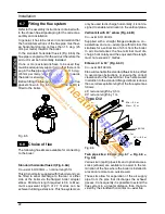
6.3
Installing the bracket
Precautions
Before mounting the bracket, check that the di-
mensions for fitting the exhaust fume duct are
complied with (refer to the leaflet included with the
flue kit, packed separately).
Utilise the paper template supplied with the boiler
to determine the fixing position for the bracket and
boiler. Securely mount the bracket to the wall
using appropriate fixings suitable for the type of
wall construction and capable of supporting the
total (wet) load. Refer to the weight given in the
technical data tables specific for each model.
IN
S
TA
LLA
TI
O
N