Instructions for use
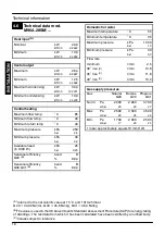
5
2.3
Ignition
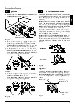
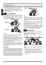
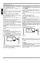
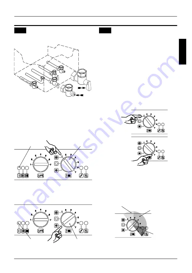
1 Check that the valves located in the lower part
of the boiler are open (Fig. 2.3).
Open position
Fig. 2.3
2 Turn on the electricity supply to the boiler,
switching on the fused spur isolation switch.
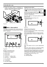
The appliance operation light 10 (Fig. 2.4) will
flash every 4 seconds (stand---by condition).
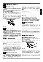
3 If the boiler is to be used for c.h. and d.h.w,
position the function selector 8 as in Fig. 2.4.
The appliance operation light 10 will flash
every 2 seconds (operating boiler).
8
10
Fig. 2.4
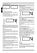
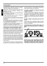
4 If d.h.w. supply only is required, position the
function selector 8 as in Fig. 2.5.
The appliance operation light 10 will flash
every 2 seconds (operating boiler).
8
10
Fig. 2.5
2.4
C.h. circuit temperature
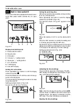
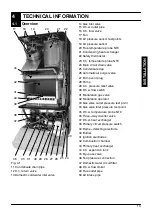
The output temperature of c.h. water is adjustable
from a minimum of about 40
°
C to a maximum of
about 85
°
C (Fig. 2.6), by turning the function se-
lector (8).
Adjustment of c.h. output on the boiler is auto-
matic. The greatest output pre---set in the factory
can, however, be reduced in level according to
actual system requirements; this does not affect
the maximum output in d.h.w. operation.
Such adjustments must be carried out by a quali-
fied person; therefore we advise you to contact
your installer or Service Agent.
Adjustment of the boiler temperature alters the
gas flow at the burner according to the thermal de-
mand in the system. So it is usual to see the burner
lit at the minimum level for more or less long
periods.
Minimum
Maximum
Fig. 2.6
Adjustment
In order to achieve optimal settings for economy
and comfort, we recommend adjusting the oper-
ating temperature of the c.h. water according to
the outside temperature, positioning the knob as
follows:
Lower than
---5
˚
C
From 5 to 15
˚
C
Between
---5 and +5
˚
C
Fig. 2.7
USE


