


- 53 -
INST
ALLA
TION
INSTALLATION
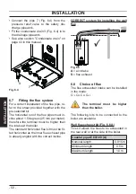
Fig. 6.11
90°=---1 m
=---0,5 m
45°
90°=---0,85 m
45°=---0,65 m
ø 60 mm
ø 60/100 mm
Each additional elbow reduces the overall
acceptable length of the flue system as fol
-
lows:
For the bend of 45° (60/100 mm) loss 0.5 m
For the bend of 90° (60/100 mm) loss
1 m
For the bend of 45° (60 mm) loss
0.65 m
For the bend of 90° (60 mm) loss
0.85 m
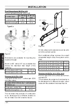
The chart Fig. 6.12 gives the maximum al
-
lowed value for
a + b
of (Fig. 6.11).
Fig. 6.12
”a” vertical length (m)
”b” horizontal length (m)
0
1
2
3
4
5
6
7
8
9
10
11
0
1
2
3
4
5
6
7
8
9
10 11
Allowed values
o d
u
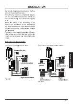
A Plume deflector is available to assist in
overcoming boundary nuisance issues.
Fig. 6.13
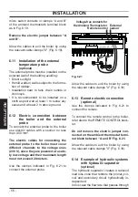
6.9 Electric connection
•
Unscrew screws "R"
and remove the front
panel "S" by pulling it and pushing it to
-
wards the top so that it is freed from the
top housing Fig. 6.14.
Fig. 6.14
R
S