


- 27 -
INST
ALLA
TION
TECHNICAL INFORMATION
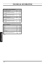
4.3
Hydraulic specifications
The hydraulic specifications represents the
pressure (available head for the central
heating system) as a function of the flow
rate.
Model
M300V.2025 SM
Fig. 4.3
0 100 200 300 400 500 600 700 800 900 1000 1100 1200 1300 1400 1500
0.00
0.05
0.10
0.15
0.20
0.25
0.30
0.35
0.40
0.45
0.50
0.55
Pressure (bar)
Flow rate (l/h)
Model
M300V.2530 SM - M300V.3035 SM
Fig. 4.4
0 100 200 300 400 500 600 700 800 900 1000 1100 1200 1300 1400 1450 1500
0.00
0.05
0.10
0.15
0.20
0.25
0.30
0.35
0.40
0.45
0.50
0.55
Pressure (bar)
Flow rate (l/h)
The boiler load loss has already been re
-
moved.
Flow rate with closed thermostatic
valves
The boiler is equipped with an automatic
by-pass, which protects the condensing pri
-
mary exchanger.
In case of excessive reduction or total
stopping of water circulation in the heating
system due to the closing of thermostatic
valves or circuit elements valves, the by-
pass ensures a minimum water circulation
inside the condensing primary exchanger.
The by-pass is calibrated to a differential
pressure of about 0.3-0.4 bar.
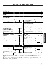
4.4
Expansion vessel
Note: this boiler is designed for opera-
tion only in a sealed central heating sys-
tem.
The height difference between the pressure
relief valve and the highest point in the sys
-
tem may be 10 m at most.
For greater differences, increase the pre-
load pressure in the expansion vessel and
the system, when cold, by 0.1 bar for each
additional 1 m.
Fig. 4.5
Total capacity
l
7,0
Pre-load pressure
kPa
100
bar
1,0
Useful capacity
l
3,5
Maximum volume of water in
the system *
l
109
* Where conditions are:
•
Average maximum temperature of the
system is 85 °C
•
Initial temperature when filling up the sys
-
tem is 10 °C
For systems with volumes
greater then the one indicated in
the above table, an additional
expansion vessel must be pro
-
vided.