- 8 -
DIAGRAMS
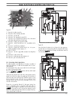
3 diaGrams
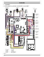
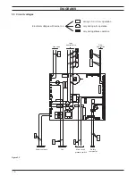
3 .1 wiring diagram inovia 25c erp - inovia 30c erp - inovia 35c erp
figure 3 .1
bk
bu
bn
bn
bu
bk
1
2
3
L
N
M
~
1
2
3
1
3
4
t
t
M
~
t
t
t
Safety
OUT
GND
5 V
OUT
GND
5 V
bn = brown
bu = blue
bk = black
wh = white
rd = red
gy = grey
gn = green
ye = yellow
vt = violet
og = orange
gnye = green/yellow
rdwh = red/white
bu
bn
bu
bn
gnye
bu
bn
bu
bu
bn
gy
bk
bu
rd
rd
bu
bk
bu
bn
gnye
wh
wh
gy
wh
wh
wh
bu
bn
bu
bn
br
bu
og
og
gnye
bu
bn
bu
bn
gnye
ye
bk
ye
wh
wh
bk
bk
rd
rd
bk
bk
bk
wh
wh
wh
wh
wh
t
wh
bk
bk
bk
bk
rd
bu
bu
bu
bu
bk
bk
wh
wh
rd
rd
rd
wh
wh
rd
rd
bu
bu
rd
rd
rd
rd
wh
wh
wh
wh
wh
bk
bk
bk
bk
diverter valve
Three way
Pump
Gas valve
Fan
Ignition
electrodes
Flame detection
electrode
Flue temp.
probe NTC
C.h. temperature
probe NTC
thermal fuse
return
C.h. temperature
probe NTC
flow
D.h.w. outlet
probe NTC
temperature
D.h.w. inlet
probe NTC
temperature
D.h.w. flow
switch
pressure switch
Primary circuit
Safety
thermostat
gn
ye
Summary of Contents for Inovia 25C ERP
Page 2: ......

