


27
14
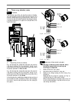
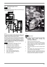
D.h.w. flow switch, filter and flow
limiter
14.1
Function
The d.h.w. flow switch
A
in Fig. 59 is a device that gener-
ates an electrical signal when hot water is drawn.
A
Fig. 59
When the flow rate through the d.h.w. circuit reaches
about 2,5 litres/min’, the float 6 (Fig. 61) is drawn to-
wards the right.
The resulting magnetic field of ring 5 increases and re-
aches the flow switch sensor 1.
The sensor generates an electrical signal that switches
the boiler d.h.w operation ON.
The state of the sensor is also indicated by means of the
lamp
B
placed on the sensor body.
B
C
Fig. 60
14.2
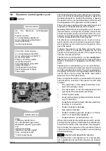
Nomenclature and location of parts
(Fig. 61)
1
Flow switch sensor
2
Body
3
O---ring
4
Spring
5
Magnetic ring
6
Float
7
Threaded ring
8
Flow limiter (M96.28SM/..., M96.32SM/... op-
tional accessory)
9
Filter
10
Spring seat
5
6
4
9
2
8
7
3
1
Fig. 61
14.3
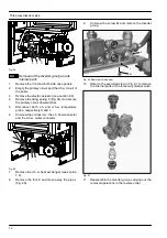
Checks
Warning: isolate the boiler from the mains
electricity supply before removing any
covering or component.
n
Flow switch sensor operation
1
Remove the front panel of the case.
2
Switch on the boiler and open a d.h.w. tap. The
lamp
B
(Fig. 60) placed on the sensor body is
switched on when the flow rate reaches about 2,5
litres/min’.
14.4
Removal of the f
low switch sensor
Warning: isolate the boiler from the mains
electricity supply before removing any
covering or component.
1
Remove the front panel of the case.
2
Disconnect the connector
C
(Fig. 60) and remove
the sensor by delicately livering downwards with
a screwdriver.


