


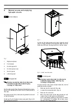


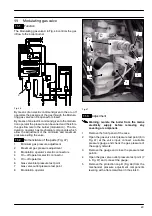

8
C
omp
on
en
ts
to
ch
ec
k
S
ec
tio
n
of
the
m
anual
!
(n
ot
e
ref
.i
n
brac
ket
s)
---
---
--- (8)
--- (7)
20.1
19.2
18.2
17.2
16
15.2
14.5
12.2
11.4
10.8
9.2
8.2
7
--- (4)
21.1
--- (3)
--- (2)
--- (1)
Loc
k---
out
sig
nal
lam
pre
d
Pre
ssure
gau
ge
Safe
tyv
alv
e
Exp
ans
ion
vesse
l
Inje
ctor
s
Flue
ther
mostat
Safe
tyth
ermosta
t
Dete
ctione
lectr
ode
Ign
ition
elec
trod
e
Air
pre
ssure
switch
Fan
and
vent
urid
evi
ce
By-
- -p
ass
val
ve
D.h.
w.t
em
p.p
rob
e
Mai
nc
irc
uitt
em
p.pr
obe
D.h.
w.f
ilte
r
Main
circu
itf
low
sw
itch
Gas
val
ve(m
odul
atin
go
perat
or)
Gas
val
ve(o
n---
off
ope
rators
)
Boil
erse
ttings
Ele
ctro
nic
p.c.
b.
Fus
es
(E
lec
tro
nic
p.c.
b.)
D.h.
w.f
low
sw
itc
h
Dive
rter
valve
Pump
D.h.
w.he
ate
xch
anger
D.h.
w.c
irc
uit
C.h.
circ
uit
Conde
nsa
te
drai
np
ipe
and
trap
Flue
pipe
s
Gas
suppl
yli
ne
Pow
ers
upply
lin
e
De
fe
ct
#
Th
e
boil
er
does
not
su
pp
ly
d.h
.w
.
(col
d
w
at
er
from
th
e
ta
p).
R
eg
ul
ar
op
er
ation
in
c/
h
m
od
e
ev
en
du
rin
g
a
drawi
ng
of
fd
.h
.w
.
J
J
J
O
n
c/
h
m
od
e
the
te
m
pe
rat
ur
e
of
the
m
ai
n
ci
rc
ui
tr
eac
hes
75
°
Ca
nd
th
e
c/
h
sy
st
em
do
es
no
th
eat
.
Th
e
bo
ile
ro
pe
rat
es
co
rrec
tly
on
d.
h.
w
.m
ode
.
J
J
In
co
rrec
tm
od
ul
at
io
n
J
J
J
N
oisy
bolie
r
J
J
Th
e
bo
ile
ro
pe
rat
es
co
rrec
tly
bu
tt
he
gas
pr
es
su
re
to
th
e
bur
ne
rr
em
ai
ns
at
min
imu
m.
J
J
F
Po
or
d.
h.
w
.t
em
pe
rat
ur
e
J
J
J
J
J
(9
)
OFF
Lo
w
d.h
.w
.f
lo
w
rat
e
J
J
J
---
W
ate
rl
ea
ks
from
th
e
sa
fe
ty
va
lv
e
du
r-
in
g
op
er
ation
on
c/
h
J
J
J
J
---
W
ate
rl
ea
ks
from
th
e
sa
fe
ty
va
lv
e
wh
en
th
e
boi
le
ri
s
of
f.
J
J
J
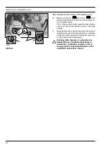
No
te
U
se
fu
lin
fo
rm
at
io
n
ca
n
be
ob
ta
in
ed
al
so
fr
om
the
op
tic
al
in
dic
at
io
n
give
n
by
the
ap
pl
ia
nc
e
op
er
-
at
io
n
lig
ht
s
(see
sec
tio
n
10.4)
.
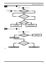
1
C
he
ck
fo
r230V~
between
lin
e
(L
)a
nd
ne
ut
ra
l(
N
)
Ve
rif
y
th
e
in
te
gr
ity
of
su
pp
ly
ca
bl
e,
pl
ug
an
d
ex
te
rn
al
fu
se
s.
C
he
ck
the
po
la
rit
y
of
line
and
ne
ut
ral
co
nne
ct
io
n
2
Ve
rif
y
th
e
tig
htn
es
s
of
th
e
ga
s
su
pp
ly
pip
e,
th
e
position
of
stop
val
ve
s.
C
he
ck
the
gas
pr
es
su
re
at
th
e
inl
et
te
st
po
in
to
ft
he
gas
val
ve
(s
ee
se
ct
.11.3)
wi
th
th
e
boi
le
ra
tr
es
ta
nd
du
rin
g
op
erat
io
n
an
d
co
mp
ar
e
it
w
ith
th
e
va
lu
es
gi
ve
n
on
th
e
in
st
alla
tio
n
bo
ok
le
t.
3
C
he
ck
fo
rs
oundne
ss
and
abs
en
ce
of
ob
st
ru
ct
io
ns
.V
er
ify
that
th
e
flu
e
te
rmin
al
is
co
rr
ect
ly
in
st
alle
d
(se
e
cle
ar
an
ce
s)
an
d
en
-
su
re
th
at
ex
haus
tg
as
is
no
ts
uc
ke
d
bac
k
by
the
bo
ile
r.
4
C
he
ck
fo
rs
oundne
ss
of
th
e
ci
rc
ui
tand
ve
rif
y
its
co
rr
ec
tfi
lli
ng
(s
ee
al
so
in
st
alla
tio
n
ma
nu
al)
.
5
A
ja
m
m
ed
by
---
pa
ss
co
ul
d
ca
us
e
th
e
ov
er
---
he
at
in
g
of
th
e
m
ai
n
ci
rc
ui
ta
nd
th
e
int
er
ve
nt
io
n
of
the
sa
fe
ty
th
er
m
os
tat
.
6C
he
ck
th
e
min
imu
m
ga
s
pres
su
re
at
th
e
ou
tle
tt
es
tp
oi
nt
of
th
e
ga
s
val
ve
(s
ee
se
ct
.1
1.
3)
and
co
m
pa
re
it
wi
th
th
e
val
ue
gi
ven
on
th
e
in
sta
lla
tion
book
le
t.
7
Ve
rif
y
the
cl
ea
nne
ss
of
in
je
ct
or
s.
8
C
he
ck
th
e
pr
essu
riz
atio
n
of
th
e
ex
pa
nsio
n
ve
sse
l.
R
ef
er
to
th
e
in
st
al
la
tion
ma
nu
al
for
pr
op
er
va
lu
es
.
9
d.
h.
w
.p
re
ssu
re
to
o
hig
h
or
flo
w
ra
te
to
o
hi
gh
.I
fn
ec
essa
ry
in
-
se
rt
a
flo
w
ra
te
lim
iter
(14.6).


