


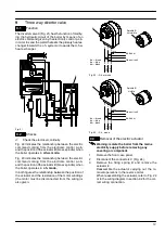


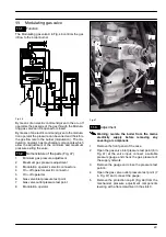


Modulating gas valve
24
B
C
Fig. 48
6
Start the boiler at its maximum power.
Operate the boiler in d.h.w. mode or ensure that
the boiler is not range rated if the test is carried out
in c.h. mode.
7
Rotate the maximum gas pressure adjustment (2
in Fig. 47) until you obtain the required pressure
(by rotating clockwise the pressure increases).
8
Turn the boiler off and disconnect one of the two
connectors (3 in Fig. 47).
9
Start the boiler and rotate the minimum gas pres-
sure adjustment (1 in Fig. 47) until you obtain the
required pressure (by rotating clockwise the
pressure increases).
10
Turn the boiler off and re---connect the wire to the
modulating operator.
11
Start the boiler and check again the maximum
gas pressure setting.
12
Turn the boiler off and disconnect the gauge.
Important: after the gas pressure checks and any
adjustment operations, all of the test points must be
sealed and replace the adjustment protection cap.
11.4
Checks
Warning: isolate the boiler from the mains
electricity supply before removing any
covering or component.
n
Check the modulation operator coil
1
Remove the front panel of the case.
2
Disconnect the connectors
D
(Fig. 50) from the
modulating operator and measure the electrical
resistance of the coil. Its electrical resistance
value must be approx. 114
Ω
*.
n
Check the on---off operators coils
1
Remove the front panel of the case.
2
Disconnect the electrical connector
E
(Fig. 50).
3
Measure the electrical resistance between the
connector pins of the on---off operators as illus-
trated in Fig. 49.
On---off operator
approx. 4 180
Ω
*
* at ambient temperature.
Fig. 49
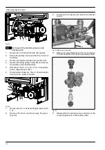
11.5
Removal of the gas valve
Warning: isolate the boiler from the mains
electricity supply before removing any
covering or component.
1
Remove the front panel of the case as explained
in the section 2.3 of this manual.
2
Disconnect the connectors
D
and
E
(Fig. 50).
3
Turn off the gas supply and disconnect the gas
isolation cock connector from the inlet port of the
gas valve.
4
Unscrew the connectors
F
and remove the pipe
G
5
Unscrew the screws
H
and remove the valve.
6
Reassemble the valve carrying out the removal
operations in reverse order.
After any service operation on the components of
the gas circuit check all the connections for gas
leaks.
Warning: After cleaning or replacement as
detailed above, if it deemed necessary to
undertake a combustion analysis, refer to
the appropriate chapter
Maintenance
of the
installation instructions manual.
D
E
F
G
H
Fig. 50


