background image

5

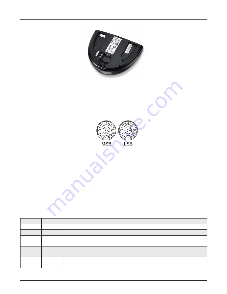
DS-4 bOttOM View

Device ID

The rotary ID switches are located on the bottom of the DS-4 and give the unit a unique Device ID. The switches are in hexadecimal 
format. All DS-4 units must have a unique Device ID to function within a Vocia Paging World (i.e., it is not possible to have two DS-4 
units with the same Device ID of hex 07). To assign a Device ID of hex 07, turn the LSB switch to 7 and leave the MSB switch on 0. 
To create an ID of hex B7, turn the LSB switch to 7 and turn the MSB switch to B. Device ID switches should be set using a 0.1 inch 
(2.5mm) to 0.12 inch (3.0mm) flat blade screwdriver. More information on setting IDs and the hexadecimal numbering scheme used 
in Vocia can be found in the Vocia Help File.

Please note

: Changes made to the Device ID while connected to the network require a power cycle in order to take effect. 

CobraNet

The DS-4 is a CobraNet device. All CobraNet routing and bundle assignments are processed by the Vocia devices locally. Vocia makes 
dynamic use of available bundles in CobraNet. Vocia devices are currently not interoperable with non-Vocia devices.  

Network Connection

The DS-4 has two RJ45 connectors located on the bottom of the unit that are labeled (1) Audio Network and (2) Option. The Audio Network 
connector should be wired to standard copper Ethernet cable to interface the DS-4 to a Vocia system via a PoE-compliant network switch. The 
Option connector is currently not used. The RJ45 connector provides two LEDs that indicate Ethernet link and network activity (see table 
below).

Left LED

Right LED

Description

None

None

No power or data connectivity. Please check the PoE network connection.

None

Green

Link established.

Flashing 
yellow

Green

Link established and CobraNet activity detected; the unit is acting as a CobraNet performer.

Flashing 
yellow

Flashing 
green

Link established and CobraNet activity detected; the unit is operating as a CobraNet conductor. 

Flashing 
yellow

None

CobraNet fault. Check cabling and configuration for errors.

Summary of Contents for Vocia DS-4

Page 1: ...Biamp Systems 10074 S W Arctic Drive Beaverton Oregon 97005 U S A 503 641 7287 www biamp com Vocia DS 4 Operation Manual ...

Page 2: ...splay 4 Microphone 4 Soft Key Buttons 4 Destination Buttons 4 Push to Talk Button 4 Bottom View 5 6 Device ID 5 CobraNet 5 Network Connection 5 Personal Identification Number PIN Security 6 Display 7 Display Status Messages 7 Device Information 7 specifications Block diagram 8 warranty 9 ...

Page 3: ...ities of all sizes Features Four user configurable page codes Four priority levels Push to Talk button with status indication Local digital signal processing including gain filters and compressor limiter Local storage of configuration data Local storage of default and or custom preambles Built in store and forward functionality CobraNet audio control with dynamic use of available bundles plus powe...

Page 4: ...of the display In the default state they are used as Next and Previous buttons to browse through the Page Codes assigned to the DS 4 If PIN security is enabled see PIN Security section of this document for more information the soft key buttons are used to accept or cancel PIN entries During a delayed page the soft key buttons are used to cancel the delayed page if required Destination Buttons Four...

Page 5: ... routing and bundle assignments are processed by the Vocia devices locally Vocia makes dynamic use of available bundles in CobraNet Vocia devices are currently not interoperable with non Vocia devices Network Connection The DS 4 has two RJ45 connectors located on the bottom of the unit that are labeled 1 Audio Network and 2 Option The Audio Network connector should be wired to standard copper Ethe...

Page 6: ...r Page Code buttons may be used to enter the required four digit PIN see button labeling examples below To enter a number the user may need to press a button multiple times as in SMS messaging During PIN entry the two Next and Previous soft key buttons on the right side of the display will display as Clear and Enter respectively Input the four digit PIN sequentially followed by the Enter key or th...

Page 7: ...ressed and the request has failed If a recorded message is associated with this Page Code please check that an MS 1 is online and configured to play the announcement 8 Please Talk Now This status message indicates that the PTT button has been pressed the page has been correctly set up in the system any assigned chime has finished playing and the audio path is open This status message corresponds w...

Page 8: ...icrophone Height Width Depth 2 1 inches 54mm 9 5 inches 241mm 7 4 inches 187mm Maximum Input 125dB SPL Mic Gooseneck Length 12 5 inches 317 5mm THD N 100Hz to 8kHz 0 05 Weight Approx 3 08 lbs 1 4kg Mic Type electret condenser Ambient Operating Temperature Range 32 113 degrees F 0 45 degrees C Mic Pattern cardioid Compliance EU Directive 2002 95 EC RoHS directive CE marked Mic Frequency Response 10...

Page 9: ...manner that does not comply with BIAMP Systems recommendations 4 Electro mechanical fans electrolytic capacitors gooseneck microphones cords connecting handheld microphones hard drives displays and normal wear and tear of items such as paint knobs handles keypads and covers are not covered under this warranty All server based devices are warranted for 3 years only 5 This warranty is in lieu of all...

Page 10: ...10 compliance ...

Page 11: ...11 compliance ...

Reviews: