A:
9300 S.W. Gemini Drive Beaverton, OR 97008 USA
T:
+1 503.641.7287
W:
www.biamp.com
10
TROUBLESHOOTING
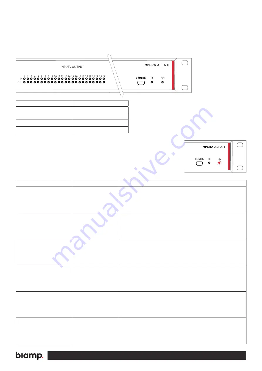
On the front of the unit you will find LED indicators used for error indication
(the “ON” LED and input/output LED number 1-6).
The “ON” LED can have the following indications:
Error indication using LEDs
If you experience a system error, the front panel “ON” LED indicator will
flash red together with some of the input/output LED indicators. You can
find the error type and possible solutions below.
Description
“ON” LED behavior
System starting
Orange non-flashing
System running
White non-flashing
System error
Red flashing
Firmware upgrade in progress
Orange non-flashing
LED shows
Description
Solution
No connection to one
or more NEB units.
• Check that the NEB units used in the project are connected.
Make sure that a NEB extender is used at the end of the connected NEB unit.
• After doing one of the above, remove the power to the control system for
20 sec before reconnecting the power again.
No project found on
the control system.
• Try to upload the project again.
• If the problem persists after several successful uploads,
contact Biamp or your local distributor.
Missing SD card or
error on SD card.
• Make sure that there is a SD card inserted in the control system.
(Look at the rear panel).
• After doing the above, turn off the power to the control system for
20 seconds before turning the power on again.
Unexpected Error.
• Turn off the power to the control system for 20 sec before turning the
power on again.
• After doing one of the above, remove the power to the control system for
20 sec before reconnecting the power again.
No contact to the
extension unit.
• Check to confirm that the serial number used in Project Designer matches
the extension unit.
• Check the network or RS-232 connection from the control system to the
extension unit.
Wrong firmware version
in Biamp extension unit.
• The extension unit has a different firmware than the one in the control system.
• Please upgrade the firmware by plugging in the USB cable from the extension
unit into a PC running Project Designer and follow the instructions.


