


INSTALLATION MANUAL
ENGLISH
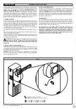
JP5
Encoder connection
WARNING!
The maximum length of the connection cable of
the encoder should not exceed 3.00 mt.
JP8
21-22
Open-Close button (N.O. Start), key selector.
21-23
Block button (N.C. Stop). If not used, leave jumped.
21-24
Photocell input (N.C.). If not used, leave jumped.
21-25
Opening limit switch connection (N.C. SWO). If not used,
leave jumped.
21-26
Closing limit switch connection (N.C. SWC). If not used, leave
jumped.
21-27
Not used
21-28
Open-Button connection (N.O. Open)
21-29
Close-Button connection (N.O. Close)
21-30
Rubber edge connection (N.C.). If not used, leave jumped.
21-31
Connection of clock input (N.O.). If the contact connected is
open, the barrier closes and gets ready for normal operation.
If the contact is closed (N.C.), the barrier opens and remains
open until contact opening.
JP9
32
Photocell check input (PHOT FAULT) (see Fig. 19)
33
Electric edge check input (EDGE FAULT) (see Fig. 19)
38-39
Antenna input for radio-receiver (38 signal - 39 braid). Cable
RG58.
11) PROGRAMMING
The control panel provided with a microprocessor is supplied with function
parameters preset by the manufacturer, suitable for standard installations.
The predefined parameters can be altered by means of either the incor-
porated display programmer or
Universal palmtop programmer
.
In the case where programming is carried out by means of
Universal palmtop
programmer
, carefully read the instructions relating to
Universal palmtop
programmer
, and proceed in the following way.
Connect the
Universal palmtop programmer
to the control unit through the
UNIFLAT accessory (See fig. 20). Enter the “CONTROL UNITS” menu,
and the “PARAMETERS” submenu, then scroll the display screenfuls us-
ing the up/down arrows, and set the numerical values of the parameters
listed below.
For the function logics, refer to the “LOGIC” submenu.
In the case where programming is carried out by means of the incorporated
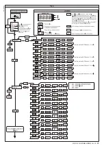
programmer, refer to Fig. A and B and to the “configuration” paragraph.
12) CONFIGURATION
The display programmer is used to set all the
LEO MV D
control panel
functions.
The programmer is provided with three pushbuttons for menu scrolling
and function parameter configurations:
+
menu scrolling/value increment key
-
menu scrolling/value reduction key
OK
Enter (confirm) key
The simultaneous pressure of the + and – keys is used to exit the active
menu and move to the preceding menu.
If the + and – keys are pressed simultaneously at the main menu level
(parameters, logics, radio, language, autosetting), programming is exited
and the display is switched off (the OK message is displayed).
The modifications made are only set if the OK key is subsequently
pressed.
When the OK key is pressed for the first time, the programming mode
is entered.
The following pieces of information appear on the display at first:
- Control unit Software version
- Number of total manoeuvres carried out (the value is expressed in
thousands, therefore the display constantly shows 0000 during the
first thousand manoeuvres)
- Number of manoeuvres carried out since the latest maintenance
operation (the value is expressed in thousands, therefore the display
constantly shows 0000 during the first thousand manoeuvres)
- Number of memorised radio control devices.
When the OK key is pressed during the initial presentation phase, the
first menu (parameters) can be accessed directly.
Here follows a list of the main menus and the respective submenus
available.
The predefined parameter is shown between square brackets
[ 0 ]
.
The writing appearing on the display is indicated between round brackets.
Refer to Figures A and B for the control unit configuration procedure.
12.1) Parameter Menu (
.0+
)
1 - Automatic Closing Time (
2!
) [ 10s ]
Set the numerical value of the automatic closing time from 1 to 180
seconds.
2 - Slow-down Distance (
!KP?JJ
) [
5
]
Set the required slow-down distance for opening and closing between
1
and
90
.
NOTE:
power failure, reset, or manual gate release, the control panel
carries out a complete manoeuvre at reduced speed, in order to learn
the length of stroke.
3- Alarm time (
?J?PKRGKC
) [ 30s ]
In the case of obstacle detection or photocell engagement, at the end
of the time set (ranging from 10s to 240s) the SCA contact is closed.
The contact is subsequently opened by the STOP command or by
triggering of the closing limit switch. Only active when the SCA Alarm
logic is set to OFF.
4- Zone (
XMLC
) [ 0 ]
Set the zone number between a minimum value of 0 and a maximum
value of
128
. See paragraph
8
on “Serial connection”.
5- Slow-down torque (
QJSBRMPOSC
) [ 99% ]
Set the motor torque value during the slow-down phase between 0%
and 99%.
6- Opening torque (
MNCLRMPOSC
) [ 70% ]
Set the motor opening torque value between 1% and 99%.
7- Closing torque (
AJQRMPOSC
) [ 70% ]
Set the motor closing torque value between 1% and 99%.
8 - Brake (
P?IC
) [ 52% ]
Set the required brake value between 0 and 99%, compatibly with the
weight of the rod and the existing stresses.
9 - Encoder (
#LAMBCP
) [ 1 ]
0: encoder disabled
: timed slow-down, obstacle detection function
not active. (The encoder can be disconnected).
1: encoder enabled
: slow-down and obstacle detection by means of
encoder
(default).
WARNING: Check that the impact force value measured at
the points established by the EN 12445 standard is lower than
that specified in the EN 12453 standard.
Incorrect sensitivity setting can cause injuries to persons or
animals, or damage to things.
10- Type of barrier (
@?PPGCP
) [1]
0:
MOOVI 30RMM/50RMM
mod. barrier
1:
MOOVI 30S
mod. barrier
2:
BGV
mod. barrier
Factory-preset value, in case of maintenance or malfunctions, check
the correspondence between the setting and the barrier model.
With the MOOVI 30RMM/50RMM barrier (0) , the following func-
tions are not active:
- slow down
- torque setting (the barrier always works at maximum torque).
With the BGV barrier (2) , the following functions are not active:
- slow down
- torque setting (the barrier always works at maximum torque).
obstacle detection.
12.2) Logic Menu (
JMEGA
)
- TCA (
RA?
) [ ON ]
ON Activates automatic closing
OFF Excludes automatic closing
- 3 Steps (
QRCN
) [ ON ]
ON Enables 3-step logic. A start impulse has the following effects:
barrier closed: ...................................................................... opens
on opening: ........................ stops and enters TCA (if configured)
barrier open: ........................................................................ closes
on closing:...................................... stops and reverses movement
after stopping: ...................................................................... opens
OFF Disables 3-step logic
- Opening Impulse lock (
'@JMNCL
) [ ON ]
ON The Start impulse has no effect during the opening phase.
OFF The Start impulse becomes effective during the opening
phase.
- Impulse lock TCA (
G@J2!
) [ OFF ]
ON The Start impulse has no effect during the TCA dwell pe-
riod.
OFF The Start impulse becomes effective during the TCA dwell pe-
riod.
- Pre alarm (
NPC?J?P+
) [ OFF ]
ON The blinker comes on about 3 seconds before the motor starts.
OFF The blinker comes on at the same time as the motor starts.
- Photocells on opening (
NFMRAMNCL
) [ ON ]
ON: In case of obscuring, this excludes photocell operation on opening.
During the closing phase, it immediately reverses the motion.
OFF: In case of obscuring, the photocells are active both on opening and
on closing. When a photocell is obscured on closing, it reverses
the motion only after the photocell is disengaged.
20
-
MOOVI 30S-30RMM-50RMM Ver. 05
D811480_05
Summary of Contents for MOOVI 30 RMM
Page 2: ...2 MOOVI 30S 30RMM 50RMM Ver 05 D811480_05 ...
Page 15: ...MOOVI 30S 30RMM 50RMM Ver 05 15 D811480_05 ...
Page 16: ...16 MOOVI 30S 30RMM 50RMM Ver 05 D811480_05 ...
Page 23: ...MOOVI 30S 30RMM 50RMM Ver 05 23 D811480_05 ...
Page 24: ...24 MOOVI 30S 30RMM 50RMM Ver 05 D811480_05 ...
Page 31: ...DGL DGL MOOVI 30S 30RMM 50RMM Ver 05 31 D811480_05 ...
Page 32: ...DGL DGL DGL 32 MOOVI 30S 30RMM 50RMM Ver 05 D811480_05 ...
Page 39: ...MOOVI 30S 30RMM 50RMM Ver 05 39 D811480_05 ...
Page 40: ...40 MOOVI 30S 30RMM 50RMM Ver 05 D811480_05 ...
Page 47: ...Fig A DGLC DGLC MOOVI 30S 30RMM 50RMM Ver 05 47 D811480_05 ...
Page 48: ...Fig B DGLC DGLC DGLC 48 MOOVI 30S 30RMM 50RMM Ver 05 D811480_05 ...
Page 55: ...DGLC DGLC MOOVI 30S 30RMM 50RMM Ver 05 55 D811480_05 ...
Page 56: ...DGLC DGLC DGLC 56 MOOVI 30S 30RMM 50RMM Ver 05 D811480_05 ...
Page 58: ...Fig 7 Fig 5 Fig 6 Fig 4 1 2 6 3 SX DX 80Nm 4 5 58 MOOVI 30S 30RMM 50RMM Ver 05 D811480_05 ...
Page 59: ...MOOVI 30S 30RMM 50RMM Ver 05 59 D811480_05 ...
Page 60: ...Fig 13 Fig 14 2 G C Fig 11 Fig 12 SWC SWO SWC SWO 60 MOOVI 30S 30RMM 50RMM Ver 05 D811480_05 ...
Page 62: ...62 MOOVI 30S 30RMM 50RMM Ver 05 D811480_05 ...
Page 63: ...MOOVI 30S 30RMM 50RMM Ver 05 63 D811480_05 ...
Page 64: ...64 MOOVI 30S 30RMM 50RMM Ver 05 D811480_05 ...
Page 67: ...MOOVI 30S 30RMM 50RMM Ver 05 67 D811480_05 ...
Page 68: ......


