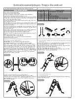
4. Remaining Steps Installation. (Figure 4):
Set up the other P6079 (steps) the same way as in step 2. Then connect
it with the other P6171 (curved handles) across the hole of the support
board and screw together with P6102 (M5X37 screw) and P6076 (M5X32
screw).
Pool Ladder Owner’s Manual
2. Steps Installation (Figure 2):
Note:
Ladder assembly requires a crosshead screwdriver or an
adjustable wrench.
Take P6193, P6194 (assemble bracing pipes) and P6079 (steps); note the
bracing pipes marking on top. Place P6193 and P6194 according to
figure 2, with the pins at a 45 degree angle to the ground. Wedge P6079
(steps) into the side of P6193 and P6194 (assembled bracing pipe) and
insert P6104 (wedge) in the steps; make sure that all "A"/"B" markings on
P6104 (wedge) are facing with the "A"/"B" markings on P6079 (steps).
Insert P6048 (bolt) with the arrow pointing to the arrow on P6104 (wedge).
Repeat the process until all P6079 (steps) are attached.
3. Knighthead/Warning Board and Curved Handle Installation (Figure 3):
Connect P6080 (assembled knighthead and warning board), with the
warning label facing the outside, with the assembled bracing pipe
(assembled P6193/P6194/P6079/P6104) and screw together with P6102
(M5X37 screw). Do not over tighten.
Connect P6171 (curved handle) with the bracing pipe (assembled
P6193/P6194/P6079/P6104) and screw together with P6076 (M5X32
screw). Do not over tighten.
5. Tighten All the Screws.
6. Test (Figure 5):
It's important to test all P6079 (steps) to make sure they are secured prior
to using.
Figure 1
1. Check the Parts
Parts contained in the group
Assembled bracing pipe, stopper A, anti-slip stopper
Assembled bracing pipe, stopper B, anti-slip stopper
Steps
wedge
Bolt (two spares)
Assembled knighthead and warning board
M5X37 screw, spacer, spring shim and M5 safety nut
M5X32 screw, spacer, spring shim and M5 safety nut
Curved handle
Parts group
P6193
P6194
P6079
P6104
P6048
P6080
P6102
P6076
P6171
Amount
2
2
4
8
18
2
4
4
2
Figure 3
Figure 2
Figure 4
Figure 5
P6104
P6048
P6079
P6193
P6194
P6076
P6102
P6171
P6080
P6080
P6171
P6193
P6194
P6079
P6104
P6102
P6076
P6048
P6076
P6102
Read all the instructions before assembling / using the ladder.
WARNING
Locate ladder on a solid base.
One person on the ladder at a time.
Ladder shall be installed per manufacturer’s instructions.
For entry / exit of pool, face the ladder at all times.
Remove and secure ladder when pool is not occupied.
No person should ever attempt to dive from ladder, pool side, or nearby object.
Ladder should only be placed in pool when proper adult supervision is
present and attentive.
Pool users should swim and play away from ladder area. Ladder may
cause injury to pool users if not regarded as a potential hazard.
Always check ladder assembly screws and retention clips before use.
This ladder is designed for use in pool only. Do not use the ladder for any
other purpose.
Note:
Do not lock the screws tight until the last step of the installation.
Keep all small ladder parts away from children’s reach.
The ladder is not a toy, use caution when using.
The 76cm (30") ladder is designed and manufactured for 76cm (30") wall
height pools.
FOLLOW AND SAVE THESE INSTRUCTIONS.
For information concerning product questions please visit our website at:
www.bestway-service.com
S-S-000602/21.0x28.5cm #58046/JS-YF-2008-B-01332/
英
S-S-000602
2


