19
►
JCOM6 / JCOM8 Pin#9 (RI) Selection Jumper
Pin
Definition
1-2 Closed
5V
3-4 Closed
RI
5-6 Closed
12V
►
JRS9 / JRS10 / JRS8 / JRS7 / JRS6 (LVDS Enable Jumper)
JRS6
Pin
Definition
1-2 Closed
Enable LVDS
2-3 Closed
Disable LVDS
JRS7 / JRS8 / JRS9 / JRS10
Jumper
1024 x 600
1024 x 768
JRS7
JRS8
JRS9
JRS10
Summary of Contents for BNX-M81
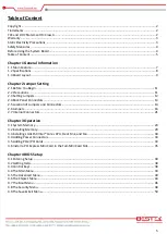
Page 1: ...1 Embedded Board BNX M81 Always at the forefront of innovation User Manual...
Page 6: ...6 Chapter 1 General Information...
Page 9: ...9 Figure 1 1 Board Layout of BNX M81 1 3 Board Layout...
Page 10: ...10 Chapter 2 Preparation...
Page 14: ...14 2 5 Locations Of Jumpers and Connectors...
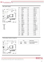
Page 20: ...20 CLR_CMOS Clear CMOS Jumper Pin Definition Open Normal Operation Close Clear CMOS...
Page 28: ...28 Chapter 3 Operation...
Page 36: ...36 Chapter 4 BIOS Setup...

