background image


11 


A  stable  and  clean  working  environment  are  essential. Dust  and  dirt  can  get  into  components and  cause  a 
malfunction. Use containers to keep small components separated. 
Adequate lighting and proper tools can prevent you from accidentally damaging the internal components. Most 
of the procedures that follow require only a few simple tools, including the following: 


A Philips screwdriver 


A flat-tipped screwdriver 


A set of jewelers Screwdrivers 


A grounding strap 


An anti-static pad 

 
Using your fingers can disconnect most of the connections. It is recommended that you do not use needle-nosed 
pliers to disconnect connections as these can damage the soft metal or plastic parts of the connectors. 


Before working on internal components, make sure that the power is off. Ground yourself before touching any 
internal  components,  by  touching  a  metal  object.  Static  electricity  can  damage  many  of  the  electronic 
components. Humid environment tend to have less static electricity than dry environments. A grounding strap is 
warranted whenever danger of static electricity exists. 


Computer components and electronic circuit boards can be damaged by discharges of static electricity. Working 
on the computers that are still connected to a power supply can be extremely dangerous. Follow the guidelines 
below to avoid damage to your computer or yourself: 


Always disconnect the unit from the power outlet whenever you are working inside the case. 


If possible, wear a grounded wrist strap when you are working inside the computer case. Alternatively, 
discharge any static electricity by touching the bare metal chassis of the unit case, or the bare metal body 
of any other grounded appliance. 


Hold electronic circuit boards by the edges only. Never touch the components on the board unless it is 
necessary to do so. Do not flex or stress the circuit board. 


Leave all components inside the static-proof packaging that they shipped with until they are ready for 
installation. 


Use correct screws and do not over tighten screws. 


2.1 Before You Begin 


Summary of Contents for BNX-M81

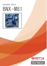
Page 1: ...1 Embedded Board BNX M81 Always at the forefront of innovation User Manual...

Page 2: ...t 15 of the FCC rules These limits are designed to provide reasonable protection against harmful interference when the equipment is operated in a residential installation This equipment generates uses...

Page 3: ...electrical discharge can damage computer components without causing any signs of physical damage You must take extra care in handling them to ensure against electrostatic build up 1 To prevent electr...

Page 4: ...pe recommend by the manufacturer Dispose of used batteries according to local ordinance Before using the system prepare basic system components If the system comes as a barebone that is none of the ke...

Page 5: ...Panel Connectors 13 2 5 Location of Jumpers and Connectors 14 2 6 Jumpers 16 2 7 Internal Connectors 21 Chapter 3 Operation 3 1 System Memory 29 3 2 Installing Memory 29 3 3 Installing LGA1150 Intel C...

Page 6: ...6 Chapter 1 General Information...

Page 7: ...ort and integrated HD graphic controller Intel Gen 4 LGA1150 Haswell Processor Two DDR3 RAM Slots up to 16GB Two SATA Ports 2 SATA 3 0 Two Display Ports VGA DVI D Ten Series Ports 2 Edge RS 232 422 48...

Page 8: ...O PS 2 2x PS 2 for Keyboard and Mouse COM 2x DB9 RS 232 Display 1x DB15 VGA 1x DVI I USB 4x USB 3 0 Ports LAN 2x RJ45 GbE Audio 3x Audio Jacks Internal I O Front Panel 1x Front Panel Switch LED Heade...

Page 9: ...9 Figure 1 1 Board Layout of BNX M81 1 3 Board Layout...

Page 10: ...10 Chapter 2 Preparation...

Page 11: ...ts Humid environment tend to have less static electricity than dry environments A grounding strap is warranted whenever danger of static electricity exists Computer components and electronic circuit b...

Page 12: ...f you remove the jumper cap or place the jumper cap on just one pin the jumper is OPEN Please see the following illustrations The illustrations on the right show a 2 pin jumper When the jumper cap is...

Page 13: ...1 PS 2 Mouse Green 2 DB15 VGA 3 DB9 RS 232 4 LAN1 5 LAN2 6 Line In Jack 7 Line Out Jack 8 Microphone Jack 9 2 USB 3 0 10 2 USB 3 0 11 DB9 RS 232 12 DVI I 13 PS 2 Keyboard Purple 2 4 Back Panel Connect...

Page 14: ...14 2 5 Locations Of Jumpers and Connectors...

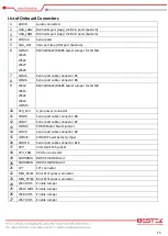
Page 15: ...485 Select Jumper for COM3 10 ATX_12V 4 pin power connector 11 COM8 Serial port cable connector 8 12 COM7 Serial port cable connector 7 13 JCOM6 COM6 Power Select jumper 14 COM9 Serial port cable conn...

Page 16: ...er 3 37 F_USB2 Front USB 2 0 header 2 38 F_USB1 Front USB 2 0 header 1 39 BATTERY Battery socket 40 LPC LPC connector 41 CI Case open intrusion header 42 CLR_CMOS Clear CMOS jumper 43 COM1 Serial port...

Page 17: ...COM3 RS 232 422 485 Selection Jumper JRS14 JRS15 JRS21 JRS19 Pin Definition 1 2 Closed RS 422 485 2 3 Closed RS 232 JCOM3 Pin Definition 1 2 Closed RS 232 3 4 Closed RS 422 5 6 Closed RS 485 2 6 Jumpe...

Page 18: ...18 COM5 RS 232 422 485 Selection Jumper JRS23 JRS22 JRS27 JRS29 Pin Definition 1 2 Closed RS 422 485 2 3 Closed RS 232 JCOM5 Pin Definition 1 2 Closed RS 232 3 4 Closed RS 422 5 6 Closed RS 485...

Page 19: ...Pin Definition 1 2 Closed 5V 3 4 Closed RI 5 6 Closed 12V JRS9 JRS10 JRS8 JRS7 JRS6 LVDS Enable Jumper JRS6 Pin Definition 1 2 Closed Enable LVDS 2 3 Closed Disable LVDS JRS7 JRS8 JRS9 JRS10 Jumper 10...

Page 20: ...20 CLR_CMOS Clear CMOS Jumper Pin Definition Open Normal Operation Close Clear CMOS...

Page 21: ...inition 1 GND 2 GND 3 12V 4 12V Pin Definition Pi n Definition 1 3 3V 13 3 3V 2 3 3V 14 12V 3 GND 15 GND 4 5V 16 PS_ON 5 GND 17 GND 6 5V 18 GND 7 GND 19 GND 8 Power OK 20 NA 9 5VSB stand by 5V 21 5V 1...

Page 22: ...22 SATA1 SATA2 Connector Pin Definition 1 GND 2 TXP 3 TXN 4 GND 5 RXN 6 RXP 7 GND 8 VCC 9 GND 4 pin CPU System Fan Connector Pin Definition 1 GND 2 12V 3 Sense 4 Speed Control...

Page 23: ...n Definition 1 5V 2 5V 3 D 4 D 5 D 6 D 7 GND 8 GND 9 10 NC Serial Port Connector Remark Pin 9 RI of COM9 COM10 can be adjusted with 5V 12V output via Jumper Pin Definition Pin Definition 1 RXD 2 DCD 3...

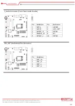
Page 24: ...ront Panel Audio Header Pin Definition Pin Definition 1 MIC_L 2 AGND 3 MIC_R 4 ACZ_DET 5 HPOUT_R 6 SRTN1 7 FAUDIO_JD 8 NC 9 HPOUT_L 10 SRTN2 SPK_OUT Audio Amplifier Connector Pin Definition 1 OUT_R 2...

Page 25: ...O70 7 GPIO17 8 GPIO71 9 SMBCLK 10 SMBDATA 11 VCC 12 GND LPT Connector Pin Definition Pin Definition 1 STB 16 GND 2 PD3 17 PD1 3 GND 18 PD7 4 GND 19 GND 5 AFD 20 GND 6 PD4 21 INIT 7 GND 22 ACK 8 GND 23...

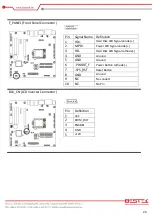
Page 26: ...Signal anode 2 MPD Power LED Signal anode 3 HD Hard Disk LED Signal cathode 4 GND Ground 5 GND Ground 6 PWRBT_F Power Button cathode 7 SYS_RST Reset Button 8 GND Ground 9 NC No connect 10 NC No Pin BL...

Page 27: ...PD0 26 GND 7 GND 27 A7P_C 8 GND 28 A6P_C 9 A1P_C 29 A7M_C 10 A0P_C 30 A6M_C 11 A1M_C 31 GND 12 A0M_C 32 GND 13 GND 33 CLK2P_C 14 GND 34 CLK1P_C 15 A3P_C 35 CLK2M_C 16 A2P_C 36 CLK1M_C 17 A3M_C 37 GND...

Page 28: ...28 Chapter 3 Operation...

Page 29: ...To install Memory 1 Make sure the Key on Memory module and slot are perfectly matched and add slowly the RAM module into the slot 2 Push the RAM module right up until the module is snapped in the slo...

Page 30: ...identally damage the socket simply by adjusting the position of the CPU Please follow the installation instructions as shown below Step A Opening the Socket 1 Push the Socket Lever down and away from...

Page 31: ...with the Pin 1 chamfer on the socket 3 Make sure that the notches on the processor align with the posts on the socket 4 Lower the processor straight down without tilting or sliding it in the socket St...

Page 32: ...processor socket Ensure that the fan power cable is on the side closet to the processor fan header 2 Align the fasteners with the corresponding board holes four of them Ensure that the fasteners slots...

Page 33: ...e 24 pin ATX Power Connector on the blue connector and 4 pin 12Vdc Power Connector on the red connector In case the 12Vdc Power Connector is not added power supply will be triggered but the motherboar...

Page 34: ...lots PCI Signal 5V or Universal PCI Yellow 1 PCIe X1 Slot PCIe 2 0 X1 Signal Good for PCIe X1 White 1 PCIe X16 Slot PCIe 3 0 X16 Signal Good for all PCIe Cards 2 Shutdown the system would be nice to c...

Page 35: ...ni Card Installation A If a screw is found in the stand off please remove the screw B Align the notch in the card with the socket key and insert the card at a slightly upward angle as shown C Push dow...

Page 36: ...36 Chapter 4 BIOS Setup...

Page 37: ...gramshouldbeexecuted underthefollowing conditions Whenchanging thesystem configurations Whena configuration erroris detectedbythe systemandyouare promptedto make changes to the Setup program Whenreset...

Page 38: ...ringthe POST TO ENTER SETUP BEFORE BOOT PRESS CTRL ALT ESC OR DEL KEY Pressthe Del keyor pressthe Ctrl Alt and Esc keysto enterSetup The online description of the highlighted setup item is displayed a...

Page 39: ...iguration Advanced Advanced system settings Chipset Chipset settings Boot System boot configuration Security BIOS security settings Save Exit Exit options as well as loading optimal defaults System Da...

Page 40: ...on is pressed Options Suspend Disabled S1 only CPU Stop Clock S3 only Suspend to RAM Default setting is S3 only Suspend to RAM S5 RTC Wake Settings Wake System with Fixed Time Disabled Enabled to wake...

Page 41: ...abled Default setting is Enabled EIST Enhanced Intel SpeedStep Technology Enable Disable Intel SpeedStep Technology Options Enabled Disabled Default setting is Enabled Turbo Mode Enable Disable CPU ov...

Page 42: ...art Fan function Options Enabled Disabled Default setting is Enabled Super I O Configuration COM 1 2 LPT Serial Port 1 Serial Port 2 Enabled to configure the serial port settings No setting would be a...

Page 43: ...tting is Enabled ISCT Notification Control Enable Disable ISCT Notification Control function Options Enabled Disabled Default setting is Enabled ISCT WLAN Power Control Enable Disable ISCT WLAN Power...

Page 44: ...Options Power On Power Off Last State Default setting is Power Off Azalia HD Audio Enable Disable onboard audio controller Options Auto Enabled Disabled Default setting is Enabled Onboard LAN1 2 Enab...

Page 45: ...ntel Virtualization Technology for Directed I O VT d feature Options Enabled Disabled Default setting is Enabled Initate Graphic Adapter Configure the primary display device Options IGD PEG IGD Defaul...

Page 46: ...d Default setting is Enabled Fast Boot Enabled to speed up the boot time by skipping a few boot procedures Options Enabled Disabled Default setting is Disabled Boot Mode Configure the boot mode UEFI B...

Page 47: ...led Default setting is Enabled Boot option filter Determines which devices system will boot at Options UEFI and Legacy Legacy only UEFI only Default setting is UEFI and Legacy Launch Storage OpROM pol...

Page 48: ...el Options Setup System Default setting is Setup Secure Boot menu Press Enter to configure the advanced items Secure Boot Support Secure Boot requires all the applications that are running during the...

Page 49: ...ot Mode Define the Secure Boot Mode Set this item to Custom to enable the advanced items configuration Option Standard Custom Default setting is Standard Key Management Press Enter to configure the ad...

Page 50: ...IOS setup Options Yes No Discard Changes Discards changes made and close the BIOS setup Save as User Defaults Press Enter on this item and then press the Y key to save as user default settings Options...

Reviews: