


16
I 0
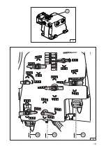
PRESENTATION OF THE CONTROL BOX
NOTE
- Fuse:
The control box (2) is protected by 3 fuses: diam. 5 x 20 mm:
- 5 Amps for the D.P. TRONIC electronic board (3),
- 10 Amps for the boom control board (4),
- 10 Amps for the boom spraying sections board (5).
Display
Electronic regulation
switches
(see manual 82465
)
Control box power
switch
Manual spraying
regulator valve
switch control
7
1
Control switches for
boom
(see manual:
AXIALE boom N° 82438
EKTAR boom N° 82461)
Plugs
2
4
3
5
6
Manual/automatic mode
switch for regulator valve
Control switch for spraying
(see pages 34 to 39)
Summary of Contents for BOXER II 3000 A
Page 2: ...2...
Page 4: ...4...
Page 6: ...6...
Page 12: ...12...
Page 20: ...20...
Page 21: ...21 OTHER SPRAYER FUNCTIONS...
Page 27: ...27 13 3 2 1 14 2 1...
Page 29: ...29 1 15...
Page 30: ...30...
Page 37: ...37 3 2 18...
Page 39: ...39 MAINTENANCE DIAGRAMS...
Page 41: ...41 574 034 3 Spraying and boom boards wiring BOXER 2 D P Tronic R...
Page 42: ...42 574 033 3 Cab connector box AXIALE front boom wiring BOXER 2 DP TRONIC R...
Page 43: ...43 574 037 3 Cab connector box EKTAR front boom wiring BOXER 2 DP TRONIC R...
Page 44: ...44 574 036 3 Cab connector box AXIALE front boom wiring BOXER 2 R...
Page 47: ...47...


