


28
82493 - ALTO
SPRAYING
- Make sure that the drain valve (V4) is closed, see the beginning of chapter "Filling", page 26 (and figure 14
page 27).
POWER TAKE-OFF SPEED
- With the power take-off connected (following filling), increase its speed to 540 rpm by bringing the needle of
the rev counter opposite the mark (R)
(see manual
No. 82.471
).
ADjUSTING THE VOLUME/HECTARE
In order to program your volume/hectare
- You need to know, for the gear chosen, the forward speed in km/h, at 540 rpm at the power take-off
(see
manual
No. 82.471
).
- Bearing in mind the required volume/hectare, refer to the rate chart of the selected nozzle(s)
(see nozzle
manual
No. 82.467
).
TO ObTAIN REQUIRED VOLUME/HECTARE
- Fit the chosen nozzles.
- Adjust the multireturn units (manual) or the compensated return (electric) according to the type and number
of nozzles on the boom sections (see page 24).
- Adjust the valves (see below).
- Increase the power take-off speed to 540 rpm.
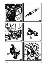
- On the manometer, display the pressure read previously on the flow table by using the manual control valve
(V) (figures 20 or 21) or the electric control valve switch (1) (figure 23) and (4) (figure 24).
- From this moment you can start spraying and you will obtain a
FIXED VOLUME/HECTARE
dose within a
wide range of power take-off speeds and therefore engine speeds.
SPRAYING CONTROL
Manual control version:
▪ Put the valve (V1) in position (figure 14, page 27).
▪ Put the supply shutters (1) of the spraying boom's sections at position
(figure 20).
▪ Put the handle of the main valve (V2) in position .
▪
With options:
Put the valves (1) and (2) in position (figure 22).
Electric control version:
▪ Put the valve (V1) in position (figure 14, page 27).
▪ Put the handle of the valve (V2) in position (figure 21).
▪
With options:
Put the valves (1) and (2) in position (figure 22).
▪ Power up the control box (1) (figure 24) by lowering the switch (2), then lower the switches (3).
TO STOP THE SPRAYING
Manual control version
(figure 20)
:
▪ Leave the supply shutters in "opened" position and adjust the main valve (V2), putting its handle in
position .
▪ All the liquid comes out of the top of the valve and goes back to the tank via the hydro injector, thus keeping
the spray well mixed, but without passing through the regulating valve.
Electric control version
(figure 24)
:
▪ PARTIAL STOP:
Lift switches (3) corresponding with the spraying sections you want to cut off.
▪ COMPLETE STOP: Lift up switch (2).
Summary of Contents for ALTO 300
Page 2: ...2 82493 ALTO...
Page 4: ...4 82493 ALTO...
Page 14: ...14 82493 ALTO...
Page 17: ...17 82493 ALTO 5 6 4 3 V4 V1 1 1 2 3 4 2 3 V2...
Page 19: ...19 82493 ALTO 7 8 1 1 2 3 4 V2 V2...
Page 21: ...21 82493 ALTO 9 10 1 V1 V2...
Page 22: ...22 82493 ALTO...
Page 25: ...25 82493 ALTO 11 12 13 1 3 2 V 1 1 3 2 V2 4...
Page 27: ...27 82493 ALTO 16 17 19 18 14 V4 V1 15 1 2 3 1 V2 V3 V2...
Page 29: ...29 82493 ALTO ON OFF 20 21 24 23 D P Elec 2 4 1 1 1 V V 22 V2 V2 1 2 3...
Page 31: ...31 82493 ALTO 27 D P Elec 1 ON OFF 28 2 4 1 1 V 26 25 V4 V1 1 2 V2 V V2 3...
Page 32: ...32 82493 ALTO...
Page 33: ...33 82493 ALTO OTHER SPRAYER FUNCTIONS...
Page 35: ...35 82493 ALTO a b a a b b 31 30 32 1 2 3 4 5 6 2 3 29 1 33 1 2 V2 V V2...
Page 37: ...37 82493 ALTO 35 36 34 V4 Alto 300 400 Alto 300 400 Alto 600 800 Alto 600 800 1 1 3 2 2 2 3 2...
Page 39: ...39 82493 ALTO 37 41 40 38 39 1 42 1 S 1 2 E...
Page 40: ...40 82493 ALTO...
Page 46: ...46 82493 ALTO...
Page 47: ...47 82493 ALTO MAINTENANCE DIAGRAM SPRAYING CIRCUIT...
Page 49: ...49 82493 ALTO 1 2 3 7 4 9 6 5 8 10 17 12 13 14 16 15 ON OFF 11...


