Bertazzoni TU64C61DX Installation, Maintenance And Use  Instructions Download Page 9


9

the symbol  

 shows the oven fan working button as to allow the oven to operates with fan assisted gas. The fan 

operation of the oven prevents the operation of the electric grill, which therefore cannot be used with the fan in action. 


the symbol  

  shows the ignition key for the oven light (all except the electric fan oven) 


the symbol  

  shows the push-button for burner ignition


the symbol  

  shows if keys are in position “on” or “off” 


USING BURNERS 

A diagram is etched on the control panel above each knob which indicates which burner corresponds to that knob. The 

burners can be ignited in different ways depending on the type of appliance and its specific characteristics: 

-  Manual  lighting  (it  is  always  possible  even  when  the  power  is  cut  off): 

Turn  the  knob  anticlockwise  that 

corresponds to the burner selected, setting it to the MAXIMUM position at the etched star (large flame Fig.23A-23B-23C) 

and place a lit match up to the burner. 

- Electric ignition:


Turn the knob counterclockwise that corresponds to the burner selected, setting it to the MAXIMUM 

position (large flame Fig. 22A-22B-22C) and keep on pressing the knob in correspondence of the ignition symbol marked 

with a star (for cookers equipped with ignition trough knob) or press the ignition button marked with a star and release it 

as soon as the burner has ignited. 

- Burner ignition equipped with safety device (thermocouple)(fig.21): 

Turn the knob anticlockwise that corresponds 

to the burner selected, setting it to the MAXIMUM position at the etched star (large flame Fig. 23A-23B-23C), press the 

knob  and  activate  one  of  the  above-mentioned  ignition  devices.  Once  ignited,  keep  pressing  the  knob  for  about  10 

seconds to allow the flame to heat the thermocouple. If the burner goes out after releasing the knob, repeat the entire 

operation. 

Note: It is recommended not to try to ignite a burner if the relative flame cap is not in the correct position. 

If the flame does not light after the first attempt, wait 5 minutes for the gas to dissipate before attempting to re-light the 

burner.  


Tips for using burners correctly: 

- Use suitable pots for each burner (see tab. 5 and Fig. 20). 

- When the liquid is boiling, turn the knob to the MINIMUM position (small flame Fig. 22A-22B-22C). 

- Always use pots with a cover. 
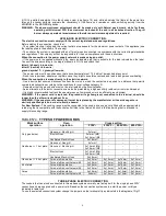
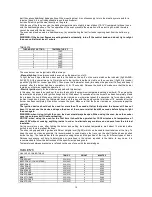


TABLE N°5 

BURNER 

PAN DIAMETER recommended (cm) 

Auxiliary 

12-14 

Semi-rapid 

14-26 

Rapid 

18-26 

Double ring 

22-26 


WARNING:  If  the  power  is  cut  off,  the  burners  can  be  lit  with  matches.  When  cooking  foods  with  oil  and  fat, 
which are very flammable, the user should not leave the appliance unattended. If the appliance is equipped with 
a glass cover, such a cover may break when heated. Turn off all burners before lowering the cover. Do not use 
sprays near the appliance when it is being used. When using the burners, make sure that the handles of the pots 
are correctly positioned. Keep children away from the appliance. If equipped with a cover, before being closed, 
any food deposits should be cleaned off  the built-in surface. 
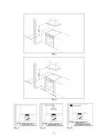
NOTE:  The  use  of  a  gas  cooking  appliance  produces  heat  and  humidity  in  the  room  where  it  is  installed. 
Therefore,  proper  aeration  in  the  room  is  needed  while  ensuring  that  natural  ventilation  openings  remain 
unobstructed (Fig.3) and activating the mechanical aeration device/exhaust hood or electric fan (Fig. 4 and Fig. 
5).  Intensive  and  continuous  use  of  the  appliance  may  require  additional  aeration,  for  example  by  opening  a 
window, or more efficient aeration by increasing the power of the mechanical exhauster, if installed. 


USING THE GAS OVEN  


GAS OVEN: 

All the gas oven cookers are equipped with a thermostat and safety device to adjust the cooking temperature. The oven 

temperature is set by turning the knob counterclockwise to match the indicator with the temperature selected. The gas 

oven can be combined with a gas grill or an electric grill. See the specific pages for use information. 

FAN GAS OVEN: 

Operating the fan of the oven by means of the appropriate switch situated on the control panel, the circulation of warm air 

guarantees a uniform heat distribution. The preheating of the oven can be avoided. However for delicate baking, it is 

preferable to warm the oven before introducing the baking-pan. The baking system with the fan convection changes in 

ATTENTION: Use pots with a flat 
bottom


Summary of Contents for TU64C61DX

Page 1: ... to property or to persons caused by incorrect installation or improper use of the appliance The manufacturer is not responsible for any inaccuracies due to printing or transcription errors contained in this booklet In addition the appearance of the figures reported is also purely indicative The manufacturer reserves the right to make changes to its products when considered necessary and useful wi...

Page 2: ...ocal environmental regulations for waste disposal For more detailed information about treatment recovery and recycling of this product please contact your local city council office INSTALLER INFORMATION The installation all adjustments transformations and maintenance listed in this part of the manual must be carried out only by skilled personnel Improper installation may cause damage to persons an...

Page 3: ...h the appliance see Fig 5 provided that there is strict compliance with the ventilation regulations APPLIANCE GAS CONNECTION Before connecting the appliance to the gas network make sure that the data on the label attached to the food warmer drawer or on the back of the cooker are compatible with what is indicated for the gas distribution network A label attached to the last page of this handbook a...

Page 4: ...chored to prevent the appliance from tilting forward and to prevent strain on the hose when the cooker is pulled forward MAKE SURE THE ANTI TILTING CHAINS ARE TAUGHT WHEN ANCHORED TO PREVENT THE APPLIANCE TILTING ADAPTATION TO DIFFERENT TYPES OF GAS FOR COOKER TYPE M6V Before performing any maintenance operation disconnect the appliance from the gas supply and electricity network REPLACING THE NOZ...

Page 5: ... the measurements indicated in table 3 TABLE N 3 Burner primary air regulation indicative BURNER Type of gas Oven mm M6 Natural fully open Universal LPG fully open 2 Burner MINIMUM adjustment Work surface burner adjustment follow the instructions below to adjust the work surface burner minimum 1 Light the burner and set the knob to the MINIMUM position small flame 2 Remove the knob of the valve th...

Page 6: ... over voltage category III Remember that the ground wire must not be interrupted by the circuit breaker As an alternative the electric connection can also be protected by a high sensitivity residual current circuit breaker It is highly recommended to attach the special green yellow ground wire to an efficient ground system WARNING If the power cord is replaced the ground wire yellow green connecte...

Page 7: ... PARTS Before performing any maintenance operation disconnect the appliance from the gas supply and electricity network To replace parts such as knobs and burners just remove them from the seats without disassembling any part of the cooker To replace parts such as nozzle supports valves and electric components follow the procedure described in the burner adjustment paragraph To replace the valve o...

Page 8: ...HOULD BE CARRIED OUT ONLY BY AUTHORISED PERSONNEL DO NOT MODIFY THIS APPLIANCE GAS BURNER DIMENSION Burner Dimension mm Auxiliary Ø 50 Semi rapid Ø 70 Rapid Ø 95 Fish 55x230 Ultra rapid Ø 130 CERAN AND ELECTRIC HOT PLATE DIMENSION TIPE OF PLATE DIMENSION Electric hot plate Ø 145 Electric hot plate Ø 180 Electric hot plate infrared Ø 145 left rear 1200W Electric hot plate infrared Ø 145 right rear ...

Page 9: ...ner Tips for using burners correctly Use suitable pots for each burner see tab 5 and Fig 20 When the liquid is boiling turn the knob to the MINIMUM position small flame Fig 22A 22B 22C Always use pots with a cover TABLE N 5 BURNER PAN DIAMETER recommended cm Auxiliary 12 14 Semi rapid 14 26 Rapid 18 26 Double ring 22 26 WARNING If the power is cut off the burners can be lit with matches When cooki...

Page 10: ... remains on otherwise repeat the operation As for cookers without ignition trough knob press the thermostat knob and the key with the spark symbol wait about 10 seconds after the burner has been completely lit and then release the knob Make sure that the burner remains on otherwise repeat the operation The ignition device should not be used for more than 15 seconds If after that period the burner ...

Page 11: ...ated by an orange light which will turn off when the temperature inside the oven is 10 C greater than the temperature setting and will turn on when the oven is 10 C less than the temper ature setting The thermostat can control the oven elements only if the relative switch is in one of the possible oven element operating modes if the switch is in position 0 the thermostat has not effect on the oven...

Page 12: ...30 minutes at a temperature of about 250 to eliminate any odours generated by the internal insulation During normal oven use select the desired cooking temperature using the thermostat knob and wait until the orange light turns off before putting in any food The oven is equipped with 5 guides at different heights fig 26 which can be used to insert shelves or the tray To keep the oven as clean as p...

Page 13: ...hout changing the taste of each food Only some models are equipped with a removable metallic filter applied to the rear screen which collects the fat while a roast is cooking Therefore it is recommended to remove this fat periodically washing the screen with soapy water and rinsing thoroughly To remove the metallic filter just apply slight pressure toward the top on the tab indicated by the arrow ...

Page 14: ...ne complete turn Then turn the knob counterclockwise so that the indicator corresponds with the selected cooking time WARNING the acoustic signal does not stop the cooking cycle The use must turn off the cooking cycle by hand using the relative knobs ANALOGUE CLOCK WITH TIMER fig 33 The analogue clock with timer lets you know when the cooking is finished thanks to an acoustic signal To set the clo...

Page 15: ... and turn off the main gas feeder valve Cleaning the work surface Periodically clean the burner heads the enamelled steel grids the enamelled covers and the flame caps using warm soapy water Then those parts should be rinsed and thoroughly dried Any liquid that overflows from pots must always be removed using a rag If it becomes difficult to open or close a valve do not force it but immediately re...

Page 16: ...16 Fig 1 Fig 2 Fig 3 Fig 4 Fig 5 ...

Page 17: ...17 Fig 6 Fig 7A Fig 7B Fig 8 Fig 9A Fig 9B Fig 10A Fig 10B ...

Page 18: ...18 Fig 11A Fig 11B Fig 12 Fig 13 Fig 14 Fig 15 Fig 16 Fig 17 Fig 18 ...

Page 19: ...19 Fig 19 Fig 20 Fig 21 Fig 22 A Fig 22 B Fig 22 C Fig 23 Fig 24A Fig 24B Fig 24C Fig 24D ...

Page 20: ...20 Fig 25A Fig 25B fig 26a Fig 26b Fig 26c Fig 26d ...

Page 21: ...21 Fig 27 Fig 28A Fig 28B Fig 28C Fig 29A Fig 29B Fig 29C Fig 30 Fig 31 Fig 32A Fig 32B Fig 32C ...

Page 22: ...22 Fig 33 Fig 34 Fig 35 Fig 36 Fig 37 Fig 38 ...

Page 23: ...n we strongly advise you contact the Bertazzoni Service Center specifying the nature of the problem the model of the equipment and the serial number This data is provided on the data label adhered to the base of the appliance and on the duplicate data label Always use original Bertazzoni spare parts BERTAZZONI GROUP ABN 38 069 686 326 650 Bridge Road Richmond Victoria 3121 Service Spare Parts 1300...

Page 24: ...310796 ...

Reviews: