


7
BEFORE LEAVING
When the installation is complete, always check for gas leaks using a soapy solution. Never use a flame to make this
check.
Ignite all burners on high flame to ensure correct operation of gas valves, burners and ignition. Turn gas taps to low
flame position and observe each burner to ensure they ignite completely at all ports and that the flame is stable. Conduct
these checks for each burner individually and concurrently.
When satisfied with the appliance, please instruct the user on the correct method of operation. In case the appliance fails
to operate correctly after all checks have been carried out, please call the
Bertazzoni Service Center
.
APPLIANCE MAINTENANCE
ATTENTION: IMPORTANT WARNINGS
For cookers resting on a base
ATTENTION: If the cooker rests on a base, take the measures necessary to prevent the cooker from sliding along the
support base.
For cookers with glass covers
ATTENTION: Before opening the appliance’s glass cover, carefully remove all liquid residues from the top of it.
ATTENTION: Before closing the appliance’s glass cover, make sure that the work surface has cooled.
For cookers with electric ovens
During use, the appliance becomes hot. Care should be taken to avoid touching heating elements inside the oven.
For cookers with electric ovens
WARNING: Accessible parts may become hot during use. To avoid burns, young children should be kept away.
For the food warmer compartment (or drop leaf in our case)
ATTENTION: The internal parts of the food warmer can become hot during use.
For glass doors
Do not use harsh abrasive cleaners or sharp metal scrapers to clean the oven door glass since they can scratch the
surface, which may result in shattering of the glass.
Do not use steam cleaners to clean the appliance.
DOOR GUARD
The M9 and M9V cookers with strips of stainless steel on the oven door can be equipped with a protective grating that
can be installed on the door. Such grating is available on the service post sale (see Fig.38).
REPLACING PARTS
Before performing any maintenance operation, disconnect the appliance from the gas supply and electricity
network.
To replace parts such as knobs and burners, just remove them from the seats without disassembling any part of the
cooker.
To replace parts such as nozzle supports, valves and electric components follow the procedure described in the burner
adjustment paragraph. To replace the valve or the gas thermostat, it is also necessary to disassemble the two rear gas
train brackets, loosening the 4 screws (2 per bracket) that attach it to the rest of the cooker and, unscrew the nuts that
attach the front burner valves to the control support, after removing all the knobs. To replace the gas or electric
thermostat, also disassemble the rear cooker guard, loosening the relative screws, to be able to pull out and reposition
the thermostat bulb.
To replace the oven bulb, just unscrew the protection cap that projects out inside the oven. (Fig.18)
WARNING: Ensure the appliance is switched off before replacing the lamp to avoid the possibility of electric
shock.
WARNING
: The power cord supplied with the appliance is connected to that appliance with a type
Y
connection (in
compliance with standards EN 60335-1, EN 60335-2-6 and subsequent amendments) for which it must be replaced by
the manufacturer or its service agent or a similarly qualified person in order to avoid a hazard.
If the power cord becomes worn or damaged, replace it based on the information reported in table 4 .
WARNING: If the power cord is replaced, the installer shall ensure that the ground cable is longer than the
phase cables and also shall comply with the warnings regarding the electric connection.
Greasing the valves:
If it becomes difficult to operate the valve, it should be greased immediately by following the instructions listed below:
1) Disassemble the valve body by loosening the two screws located on the body of the valve.(Fig.19)
2) Extract and clean the seal cone and its housing with a rag soaked with thinner.
3) Lightly grease the cone with a special grease.
4) Insert the cone, moving it several times, remove it again, remove the excess grease and make sure that the gas
passage ways are unobstructed.
Summary of Contents for TU64C61DX
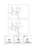
Page 16: ...16 Fig 1 Fig 2 Fig 3 Fig 4 Fig 5 ...
Page 17: ...17 Fig 6 Fig 7A Fig 7B Fig 8 Fig 9A Fig 9B Fig 10A Fig 10B ...
Page 18: ...18 Fig 11A Fig 11B Fig 12 Fig 13 Fig 14 Fig 15 Fig 16 Fig 17 Fig 18 ...
Page 19: ...19 Fig 19 Fig 20 Fig 21 Fig 22 A Fig 22 B Fig 22 C Fig 23 Fig 24A Fig 24B Fig 24C Fig 24D ...
Page 20: ...20 Fig 25A Fig 25B fig 26a Fig 26b Fig 26c Fig 26d ...
Page 22: ...22 Fig 33 Fig 34 Fig 35 Fig 36 Fig 37 Fig 38 ...
Page 24: ...310796 ...