


8
5) Replace all the pieces by reversing the order in which they were disassembled and check that the valve operates
correctly.
6)To replace the power cable, lift the terminal board’s cover and replace the cable. To access the terminal board in
cookers with a 3x2.5mm² cable, the back panel on the rear of the appliance must be removed.
USE AND MAINTENANCE MANUAL
WARNING: This appliance is not intended for use by persons (including children) with reduced physical,
sensory or mental capabilities, or lack of experience and knowledge, unless they have been given supervision
or instruction concerning use of the appliance by a person responsible for their safety.
WARNING: Children should be supervised to ensure that they do not play with the appliance.
DO NOT USE OR STORE FLAMMABLE MATERIALS IN THE APPLIANCE STORAGE DRAWER OR NEAR THIS
APPLIANCE.
DO NOT SPRAY AEROSOLS IN THE VICINITY OF THIS APPLIANCE WHILE IT IS IN OPERATION.
DO NOT STORE OR USE FLAMMABLE LIQUIDS OR ITEMS IN THE VICINITY OF THIS APPLIANCE.
WHERE THIS APPLIANCE IS INSTALLED IN MARINE CRAFT OR IN CARAVANS, IT SHALL NOT BE USED AS A
SPACE HEATER.
WARNING: SERVICING SHOULD BE CARRIED OUT ONLY BY AUTHORISED PERSONNEL.
DO NOT MODIFY THIS APPLIANCE.
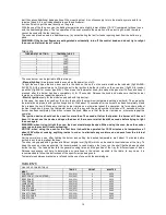
GAS BURNER DIMENSION
Burner
Dimension (mm)
Auxiliary
Ø 50
Semi-rapid
Ø 70
Rapid
Ø 95
Fish
55x230
Ultra-rapid
Ø 130
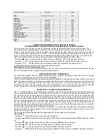
CERAN AND ELECTRIC HOT PLATE DIMENSION
TIPE OF PLATE
DIMENSION
Electric hot plate
Ø 145
Electric hot plate
Ø 180
Electric hot plate infrared
Ø 145 left rear 1200W
Electric hot plate infrared
Ø 145 right rear 2100W
Electric hot plate infrared
Ø 145 right front 1200W
Electric hot plate infrared
Ø 180 left front 1700W
Electric hot plate hi light
Ø 145 left rear 1200W
Electric hot plate hi light
Ø 170/265 left rear 1400/2200W
Electric hot plate hi light
Ø 145 left rear 1200W
Electric hot plate hi light
Ø 180 left rear 700/2100W
CONTROL PANEL DESCRIPTION
On the control panel, small symbols show the function of each knob or key. Here as follows are the several controls that
a cooker can have:
the symbol
shows the disposition of burners on the worktop, the full dot identifies the burner in object (in this
case the rear burner on the right).
the symbol
shows the running of any oven (gas oven with gas grill, gas oven with electric grill, static oven, 9
positions switch)
the symbol
shows the electric thermostat for electric fan oven
the symbol
shows the minute minder
the symbol
shows the operating key for the rotisserie (only gas oven)
Summary of Contents for TU64C61DX
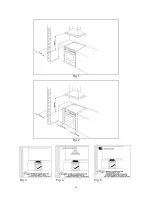
Page 16: ...16 Fig 1 Fig 2 Fig 3 Fig 4 Fig 5 ...
Page 17: ...17 Fig 6 Fig 7A Fig 7B Fig 8 Fig 9A Fig 9B Fig 10A Fig 10B ...
Page 18: ...18 Fig 11A Fig 11B Fig 12 Fig 13 Fig 14 Fig 15 Fig 16 Fig 17 Fig 18 ...
Page 19: ...19 Fig 19 Fig 20 Fig 21 Fig 22 A Fig 22 B Fig 22 C Fig 23 Fig 24A Fig 24B Fig 24C Fig 24D ...
Page 20: ...20 Fig 25A Fig 25B fig 26a Fig 26b Fig 26c Fig 26d ...
Page 22: ...22 Fig 33 Fig 34 Fig 35 Fig 36 Fig 37 Fig 38 ...
Page 24: ...310796 ...