background image


English 


17 

4.3.2


Menu 

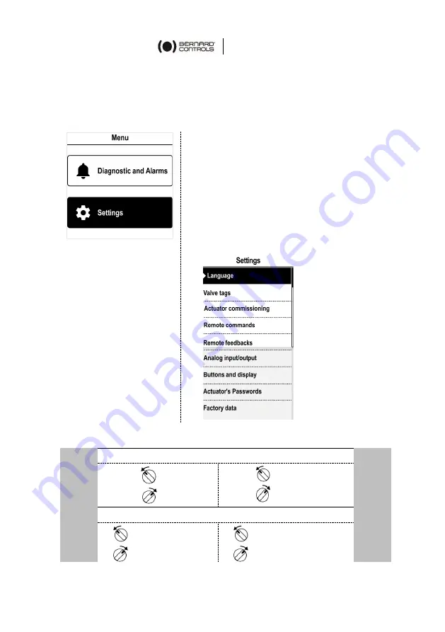
The Menu screen has 2 main sections: 

-


Diagnostic and Alarms 

-


Settings 


The Menu screen has 2 main sections: 


Diagnostic and Alarms


Settings 

is used


to check or change 

the 

actuator’s settings

: valve tag, 

password, torque limits, Bluetooth

®

etc.


The 

Factory data 

submenu contains 

the 

actuator’s 

characteristics (see 

Appendix IV).


How to use the knobs 

Left 

knob


Menu navigation 

Right 

knob


 ESC 


OK


(up)


(down)


Edition 


(1 digit left)


(1 digit right)


(decrease values)


+


(increase values)


Summary of Contents for AT LOGIC v2

Page 1: ...AT LOGIC v2 RANGE Start Up Guide SUG_17011_EN Ind E Art 5100582 ...

Page 2: ......

Page 3: ... wiring 3 4 Closing the control compartment 3 5 Wiring the external ground terminal 4 ACTUATOR CONTROLS 15 4 1 Control panel 4 2 Control modes 4 3 Local control with the Control panel 4 4 Local control with the Smartphone application 4 5 Remote controls 4 6 Analog Input Output OPTION 5 COMMISSIONING 23 5 1 Setting the display language 5 2 Valve tags 5 3 Actuator Commissioning setting 5 4 Setting t...

Page 4: ...lays configuration 5 8 Setting the forced local mode with BC App 6 OPERATION 63 6 1 Emergency Manual Command 6 2 Local control operation APPENDIX 64 I Starting with BC App II Alarms and Settings menu tree options not detailed III Diagnostic and Alarms list IV Factory data menu tree ...

Page 5: ...S Tip or info Warning requiring a check and or a compulsory action Warning requiring a check and or a compulsory action on the device because of risks of damages for the device or danger for the staff working on the device ...

Page 6: ...ntract 2 1 1 Check identification sticker The information on the nameplate sticker on the side of the actuator should match your order The QR code on this sticker can be used to identify the actuator 2 2 Storage Actuators should be stored under a shelter in a clean and dry place and at a stable ambient temperature Avoid placing the actuator directly on the floor Check that the cable entry plugs ar...

Page 7: ...lity 4 Manually operate the actuator in both directions for a couple of turns What to check on pre installed actuators If you expect a long delay between actuator valve mounting and electrical wiring visually check that the cable entries and cover are tightly closed 2 3 Maintenance All AT actuators feature lifetime lubrication They require no specific maintenance under the condition that they were...

Page 8: ... order to wire the actuator When opening the compartment unplug the control panel cable from the main board in order to avoid damaging it How to remove the cover 1 With a 10 mm angled socket wrench or flat blade screwdriver unscrew the 4 screws securing the cover to the housing 2 Pull out the cover along its axis 3 When the cover plug is accessible unplug it from the main board 4 Remove the cover ...

Page 9: ...entries 6 Main board 7 4 Relay board OPTION 8 AI AO board OPTION 9 Bus board OPTION 10 Modular reduction gear The control panel board is attached to the actuator cover Do not supply the wires with electrical power before the wiring is finished and the control compartment is closed Make sure to cut off the actuator s power supply when opening the control compartment 1 2 3 4 5 6 7 10 8 9 ...

Page 10: ...he cable entry 4 Insert the sealing nut on the cable and pass the cable through the cable gland 3 3 3 Wiring power and control cables Terminal board On a side of the electronics assembly there are a screw terminal block to connect command and signaling A 3 push on connectors to connect the power supply B Control terminals 1 36 Power connectors 3Ph 1Ph 3Ph L1 L2 L3 with phase correction 1Ph L Live ...

Page 11: ...art which is fixed to the board 3 Using a crimping tool connect the power supply to the female push on connectors 4 Place back the female connectors on the male connectors marked L1 L2 L3 3Ph or L N 1Ph depending on the power supply phase 5 Using a crimping tool attach the end of the ground cable to the ring lug 6 Using a 4 mm hex key secure the ground cable to the ground terminal 7 Using a 3 0 5 ...

Page 12: ...current 500 mA Fuse size mm inches 6 3 32 1 Voltage rating VAC 500 V Blow characteristic Fast acting Breaking current capacity current AC 1 kA 3 3 5 Relays The AT Logic is equipped with a Fault relay and 3 signaling relays See list of Fault relay Alarms in Appendix III This list cannot be modified Customizable relays Out of the 3 signaling relays one is customizable A 4 Relay board can be added as...

Page 13: ... a heating resistance As soon as the actuator is installed in the field it is required to supply the resistance to prevent condensation Immediately put the cover back in place after installation and make sure that its seal is clean Never leave the actuator s electrical components without their protection cover In case of water intrusion Dry the electrical components before putting back the cover C...

Page 14: ...d 1 Put back the cover making sure that the screen is correctly oriented for operation and place it on the housing 2 With a 10 mm angled socket wrench or flat blade screwdriver secure the cover to the housing with the 4 screws 3 5 Wiring the external ground terminal 1 Crimp the end of the ground cable with a 6 mm ring lug 2 Using a 5 mm Allen key fix the ground cable on the housing next to the cab...

Page 15: ...s are deactivated The actuator is set to Local at startup The control mode can be locked with an optional padlock at the bottom of the control panel Knobs The knobs are used for operation upper function or menu navigation lower function Once released these knobs return to the center position LEDs The LEDs indicate the actuator status CLOSED or OPEN Default colors are red for CLOSED and green for O...

Page 16: ...ication This mode first needs to be authorized see 5 8 4 3 Local control with the Control panel 4 3 1 Operation Operation screen indicates Top actuator ID and status icons warning alarm Bluetooth activated Bluetooth activated with device connected Local command inhibited Center current position of the valve either CLOSED current percentage between 0 and 100 depending on the travel direction or OPE...

Page 17: ...and Alarms Settings is used to check or change the actuator s settings valve tag password torque limits Bluetooth etc The Factory data submenu contains the actuator s characteristics see Appendix IV How to use the knobs Left knob Menu navigation Right knob ESC OK up down Edition 1 digit left 1 digit right decrease values increase values ...

Page 18: ...s Top 1 Access to main menu 2 Alternately valve tag and mainboard reference or control mode 3 Warnings or alarms if any Center current position of the valve either CLOSED opening percentage between 0 and 100 or OPEN The following functions are used to operate the actuator decreases increases the opening target with one or several taps closes opens the valve Only with the Positioner option drag to ...

Page 19: ...tor settings Quit Actuator Account account data Assistance assistance information 4 4 3 Settings screen From the main menu you can access the settings The Settings Menu has 2 main sections Top Section access to main menu then valve tag and mainboard reference Settings list Valve identification Commissioning of valve Inputs Outputs Bus Actuator local settings Access code definition Reset to factory...

Page 20: ... CLOSE If the STOP local command button is not used do not connect the STOP wire The OPEN or CLOSE contact must be maintained to operate the actuator 4 5 1 Single switch control Dry Contact The actuator can be controlled via a single external switch Opening Closing O Open C Close Switch closed valve opens Switch open valve closes Switch closed valve closes Switch open valve opens The actuator must...

Page 21: ...op C Close O Open A jumper must be fitted across customer terminal 9 10 Remote commands can be used either in AC or DC voltage Use terminal 10 for voltage from 10 to 60V Use terminal 11 for voltage from 90 to 250V It is imperative to comply with the voltage ranges mentioned above otherwise components will not function or will be damaged For AUX1 AUX2 auxiliary commands these commands can be assign...

Page 22: ...the operating range of the actuator The input signal is isolated from the ON OFF commands and from the remote position signal The actuator can still be operated in ON OFF mode with the Open Close and Stop commands or using Proportional control One of the auxiliary commands must be used to select between these 2 control modes In the standard configuration Auxiliary Command is set on Proportional ON...

Page 23: ...Local mode Accessing the actuator menu To change the actuator s settings or check the active warnings and alarms use the Control Panel or the BC App to access the actuator s menu It is your responsibility to set the security of the Local Commands Control Panel or Smartphone Application for your process The default position of the Control selector button should be on Remote The Access Code of the a...

Page 24: ...hem How to enter the access code with Control panel 1 Turn the left knob to the right and hold 2 Turn the right knob to the left and to the right The following screen appears 3 Enter the access code a Set the digit value with and on the right knob b Select with OK on the left knob when the value is right c Set the following digit 9000 If you validate an incorrect value choose ESC with the left kno...

Page 25: ...g 10s The following screen appears 3 Select YES then validate with OK The access codes are now reset to 0000 and 9000 and can be reprogrammed How to change the access codes The Bluetooth access codes can only be changed using Read Write mode 1 Go to Settings Actuator s Passwords The following screen appears 2 Choose the correct access code option to change Access code to Read Write or Access code ...

Page 26: ...left knob 4 When all digits are set select Save and validate with OK on the left knob 5 Return to the main menu or quit the settings with several ESC How to change the access codes with BC App 1 Go to Main Menu 2 Select Settings Actuator passwords and security The following screen appears ...

Page 27: ...English 27 3 Select the Password you want to change 4 Enter your new password and confirm it 5 Tap on OK to validate ...

Page 28: ... display language 1 Enter the menu then navigate to Settings Language The following screen appears 2 Select the language with or on the right knob then confirm with OK on the left knob 3 Go to SAVE with or on the right knob then validate with OK on the left knob ...

Page 29: ... the Valve TAG box 3 Define the Valve TAG with or on the right knob 4 Go to SAVE with or on the right knob then validate with OK on the left knob 5 2 2 How to change the location or process 1 Enter the menu then go to Settings Valve Tags The following screen appears 2 Select Location or Process box 3 Define the Location or Process with or on the right knob 4 Go to SAVE with or on the right knob th...

Page 30: ...sing direction may change How to change closing direction 1 Enter the menu and navigate to Settings Actuator commissioning Set closing direction 2 Choose the closing rotation direction required Clockwise or Counter clockwise with or on the right knob then confirm with OK on the left knob 3 Go to SAVE with or on the right knob then validate with OK on the left knob ...

Page 31: ...r on the right knob then confirm with OK on the left knob 3 Select Save then validate with OK on the left knob 5 3 3 Setting the torque limits This setting allows to set torque limits at the main steps of the travel at the beginning Break during the travel Run and at the end of the travel End Limits are In closing direction Break to Close BTC Run to Close RTC End to Close ETC Tight zone In opening...

Page 32: ...oning 2 Select Set torque limits and validate with OK on the left knob 3 Select closing or opening direction and validate with OK on the left knob The following screen appears 4 Select the limit to modify with or on the right knob then validate with OK on the left knob The following screen appears ...

Page 33: ...o limit checkbox is filled in when the option is selected To set No limit make sure the checkbox is filled in validate with OK and confirm using OK again To correct the set value go to the 3rd digit with then to the previous digits with ESC and review a or b sub steps to set a new value When done go to Continue with then validate with OK on the left knob The torque limit settings page appears ...

Page 34: ...he End limit and the Tight zone Set each digit value with or on the right knob then validate with OK on the left knob Validate Continue with OK on the left knob 7 When all limits are set select Save and validate with OK on the left knob ...

Page 35: ...could lead to an actual torque on the valve seat higher than the limit set How to set the overtorque limiter 1 Enter the menu then navigate to Settings Actuator Commissioning The following screen appears 2 Select Overtorque Limiter on valve seat The following screen appears 3 Select Enable Disable then confirm with OK on the left knob 4 Go to Save with or on the right knob then validate with OK on...

Page 36: ... first one set How to set CLOSED and OPEN position 1 Enter the menu then navigate to Settings Actuator Commissioning Set closed position depending on your needs The following screen appears 2 Close the valve using the closing knob 3 When the valve is closed validate Save with OK on the left knob The following screen appears 4 Select Confirm with OK on the left knob The following screen appears ...

Page 37: ...o small the following error screen appears Select Try again with OK on the left knob and continue to open the valve When the correct position is reached select Save with OK on the left knob The following screen appears 6 Select Confirm with OK on the left knob Closing and opening positions are set Once end positions are set proceed to an operation in each direction to check the settings ...

Page 38: ...eed at closing Normal speed at opening Slow motion at opening The following options are available Beginning of slow motion zone opening closing direction End of slow motion zone opening closing direction Slow motion duration Total opening closing time is the result of slow motion duration and normal speed duration How to set the timer 1 Enter the menu then navigate to Settings Actuator Commissioni...

Page 39: ...with OK on the left knob The following screen is displayed 3 Select Beginning of Slow Motion Zone The following screen appears 4 Set the position in between Closing 0 and Opening 100 and confirm with Continue 5 Select End of Slow Motion Zone The following screen appears ...

Page 40: ... screen appears 9 Set the duration then confirm with Continue The total operating time will be calculated and is shown in the Total Opening Time screen for total opening or closing time If not activated is displayed the slow motion duration defined is too short 10 Go to Save with or on the right knob then validate with OK on the left knob ...

Page 41: ...y settings can be selected in Settings Buttons and display 5 4 1 How to change the language In addition to the Settings Language screen the language display can be selected in this menu 1 Enter the menu then go to Settings Buttons and Display The following screen appears ...

Page 42: ... validate with OK on the left knob The following screen appears 3 Choose the desired language with or on the right knob and confirm with OK on the left knob 4 Go to SAVE with or on the right knob then validate with OK on the left knob ...

Page 43: ...al 1 Enter the menu then navigate to Settings Buttons and Display The following screen appears 2 Select Units and validate with OK on the left knob The following screen appears 3 Choose the appropriate units with or on the right knob and validate with OK on the left knob 4 Go to Save with or on the right knob and confirm with OK ...

Page 44: ...the physical orientation of your actuator 1 Enter the menu then go to Settings Buttons and Display The following screen appears 2 Select Screen orientation and validate with OK on the left knob The following screen appears 3 Select the rotation angle matching the actuator orientation Angle values are counterclockwise ...

Page 45: ...alidate with OK on the left knob The display rotates accordingly 5 4 4 How to choose green or red LED color for open position The LED color configuration can be adjusted depending on the local standards How to set LEDs configuration 1 Enter the menu then go to Settings Buttons and Display The following screen appears ...

Page 46: ...o LED color and validate with OK on the left knob The following screen appears 3 Select the corresponding setting and validate with OK on the left knob 4 Go to Save and validate it The following screen appears 5 Select YES and validate ...

Page 47: ...and Display The following screen appears 2 Go down in the menu to LED in intermediate position and validate with OK on the left knob The following screen appears 3 Select the appropriate setting then validate with OK on the left knob 4 Got to Save and validate The confirmation screen appears 5 Select YES and validate ...

Page 48: ...mmand Maintained mode turn and hold the knob to send a command The command will stop when the knob is released Proportional mode turn the knob to define a precise target percentage of opening 1 Enter the menu and navigate to Settings Buttons and Display The following screen appears 2 Go down in the menu to Button mode and validate with OK on the left knob The following screen appears ...

Page 49: ...ptions are available Local Remote option enables remote control or local control from a remote location Local Remote Remote option enables remote and local control from a remote location Local command inhibition option allows a remote command to override local commands even if Local Remote selector is on Local on the actuator Opening inhibition prevents the actuator from opening Closing inhibition...

Page 50: ...de by closing a contact How to set the remote stop command 1 Navigate in the menu to Settings Remote Commands The following screen appears 2 Go down in the menu select Remote Stop and validate with OK on the left knob The following screen appears 3 Select the STOP mode Normally opened or Normally closed 4 Go down to Save and validate with OK on the left knob The confirmation screen appears 5 Selec...

Page 51: ...r remote command 1 Navigate in the menu to Settings Remote commands The following screen appears 2 Go down in the menu list select Priority and validate with OK on the left knob The following screen appears 3 Select the priority action in the list then validate with OK on the left knob 4 Go down to Save and validate with OK on the left knob The following screen appears 5 Select YES and validate ...

Page 52: ...ortional command such as a 4 20 mA analog signal How to activate the positioner function 1 From the Analog Input Output menu enter Positioner Activation The following screen appears 2 Select Enable and confirm with OK on the left knob 3 Go to Save then validate with OK on the left knob The confirmation screen appears 4 Select YES then validate with OK on the left knob The Analog Input Output menu ...

Page 53: ...settings Select the setting to adjust and validate with OK on the left knob The corresponding setting screen appears Select the desired option and validate with OK on the left knob The Continue button is highlighted validate with OK on the left knob The display goes back to Input signal type screen If you choose 0 20mA or 0 10V the switch on the positioner board needs to be switched from the mA to...

Page 54: ...back signal 1 From the Analog Input Output menu enter Positioner feedback signal The following screen appears 2 For the Feedback Signal Type Feedback Signal Direction and Feedback Signal Wiring settings Select the setting to adjust and validate with OK on the left knob The corresponding setting screen appears Select the desired value and validate with OK on the left knob The Continue button is hig...

Page 55: ...ut signal to deviate from the actual actuator position without making any correction This setting is made at the factory but it is possible to adjust it If the dead band is too narrow the actuator could hunt moving back and forth in an attempt to reach the input signal value without stopping within the dead band If the dead band is too wide positioning operations are less precise The default dead ...

Page 56: ...tive in the standard configuration and the actuator remains in its position if the input signal is lost How to set the Position on Loss of Setpoint 1 From Analog Input Output menu enter Position on Loss of Setpoint The following screen appears 2 Select the desired value and validate with OK on the left knob 3 Navigate to Save and validate with OK on the left knob The confirmation screen appears 4 ...

Page 57: ...ng accuracy by self learning algorithm 1 From the Analog Input Output menu enter Improved positioning accuracy by self learning algorithm The following screen appears 2 Select YES or NO and validate with OK on the left knob 3 Go to Save then validate with OK on the left knob The confirmation screen appears 4 Select YES then validate with OK on the left knob The Analog Input Output menu is then dis...

Page 58: ...e procedure for optional relays 1 Navigate in the menu to Settings Remote feedbacks The following screen appears 2 To set a signaling relay select it and validate with OK on the left knob 3 The following screen appears 4 To set the condition select the Contact closed or Contact open option then validate with OK on the left knob 5 Select Continue and validate with OK on the left knob 6 For Signalin...

Page 59: ...n OFF mode Local mode Remote mode Stopped in intermediate position Motor Thermal Overload Jammed Valve Phase Loss Power ON Handwheel action Actuator controlled by Fieldbus Overtravel Relay operated by Fieldbus 7 Several options can be selected by navigating to the option and selecting each one with OK on the left knob 8 Go to Save and validate with OK on the left knob The following screen appears ...

Page 60: ...etooth b Switch to Local mode within BC App 5 8 1 Switch Local Remote Mode How to allow switch local remote mode 1 Navigate in the menu to Access code to Read and Write 2 Go to Settings Actuator s Passwords The following screen appears 3 Go down in the menu to Switch Local Remote Mode and validate with OK on the left knob 4 The following screen appears 5 To allow switch to Local Remote control wit...

Page 61: ...ocal control within BC App You can only proceed to this operation if the Control selector is on Remote on the actuator and the actuator s Switch Local Remote Mode is set to Switch to local mode allowed How to switch to Local control with App 1 Navigate to the Operate screen If the switch is inhibited an Info button replaces the Edit button ...

Page 62: ...Edit The App asks for confirmation 3 Tap on Switch to Local Mode Remote mode becomes Local mode The actuator can now be operated as if it was set on Local mode To get back to Remote mode simply tap again on the Edit button ...

Page 63: ...To use Local control mode with Control panel see 4 3 Local control mode with Smartphone see 4 4 Forced Local control mode from Remote mode with Smartphone see 5 8 how to allow modes switch then switch modes and 4 4 to use Local mode with Smartphone Beware the declutch isautomatic Use the Manual Command only when the electric motor commands are inactive or the local knob is on OFF When using the Po...

Page 64: ...ion 1 Go to your app store and search for Bernard Controls 2 Once found download and install BC App Once installed start the App Log in or follow the free account creation screen sequence if it is your first start An Internet connection is required on your smartphone ...

Page 65: ...log into your account 2 Once logged in the App will start to scan for nearby actuators 3 If the desired actuator is found select it If not retry or scan the actuator QR code on the sticker or enter its serial number or 4 Check that you are connected to the correct actuator the 2 LEDs in front of the actuator should blink and the Bluetooth icon on the screen has between then enter the Access code ...

Page 66: ...ation or process Actuator commissioning Set closing direction Closing Opening Type Set torque limits Overtorque Limiter on valve seat Set closed position Set open position Speed Control Timer Remote commands Auxiliary remote command 1 Auxiliary remote command 2 Remote stop Priority Remote feedbacks Signaling relay 1 Signaling relay 2 Signaling relay 3 ...

Page 67: ...s Refer to appropriate guide Modbus Refer to appropriate guide Buttons and display Language Units Screen orientation LED Color LED in intermediate position Button mode Actuator s Passwords Access code to Read only Access code to Read Write Switch Local Remote Mode Bluetooth activation Factory data For more detail see Appendix IV Actuator type Mechanical features Motor features Electrical features ...

Page 68: ... rotation Configuration memory fault There is an error in the stored configuration data Lost phase 3 phase motor There is a phase missing on the 3 phase supply Thermal overload The thermal switch of the motor was tripped Valve jammed The maximum torque was reached during operation Lost signal 4 20mA The 4 20 mA signal has been lost Communication fault between main board and HMI The communication b...

Page 69: ...s not working The main board has been damaged Local Button fault The buttons are not working Selector Off activated The selector button is in the OFF position Selector Local activated The selector button is in the Local position Position fault 10 and 110 The position is outside the range Auxiliary command 2 internal error Auxiliary command 2 is in fault The main board has been damaged Actuator hun...

Page 70: ...te Duty Class Max Temperature Min Temperature Output Flange Environment Corrosivity Lubricant Type Lubricant Quantity Motor features Supply Voltage V Frequency Hz Motor speed rpm Motor power kW Motor Duty Nominal Current A Starting Current A Electrical features Wiring Diagram Dimensional Drawing AI AO Board 4 Extra Relay Board Bus type Firmware Profibus Modbus board version OPTIONS Main board vers...

Page 71: ......

Page 72: ...PE BELGIUM BERNARD CONTROLS BENELUX NIVELLES BRUSSELS inquiry belgium bernardcontrols com inquiry holland bernardcontrols com Tel 32 0 2 343 41 22 FRANCE BERNARD CONTROLS FRANCE BERNARD CONTROLS NUCLEAR FRANCE GONESSE PARIS inquiry france bernardcontrols com Tel 33 0 1 34 07 71 00 GERMANY BERNARD CONTROLS DEUFRA TROISDORF KÖLN inquiry germany bernardcontrols com Tel 49 2241 9834 0 ITALY BERNARD CO...

Reviews: