


SUCTION PIPING
Refer to illustrations on Page 10 and 11 for recommended and
not recommended practices in suction connections.
DISCHARGE PIPING
Refer to illustrations on Page 12 and 13 for recommended and
not recommended practices in discharge connections.
REQUIREMENTS FOR PROPER OPERATION
Pump End:
When delivering the required capacity (GPM) to the system
piping, the pump must add the amount of Head required by
the system at that capacity. The operating head-capacity point
should be as close as possible to the highest efficiency line
shown on the performance curve, and MUST be below the
head-capacity line labeled “Maximum” RPM. The maximum
operating RPM for the pump is determined by bearing life, or
in some cases, by the pressure limits of the pump. “The
maximum working pressure for NPT tapped and flanged
pumps, per ANSI B16.1 class 125, is 175 PSI unless
otherwise stated on the pump curve”. When used as a booster
pump, the pressure at the pump discharge (combination of
inlet pressure plus pressure added by the pump) must not
exceed the maximum working pressure shown. The Suction
NPSHA must be greater than the NPSHR shown on the pump
curve.
Engine:
The engine used to drive the pump must be suitable for the
application. It must produce adequate power for the pump
demand, and must rotate in the correct direction (standard
rotation is CLOCKWISE when viewed from the front of
engine).
Internal Combustion Engines are variable speed and variable
power machines. The power output depends upon the engine
speed (RPM) and will be reduced when operating altitude,
and/or the air temperature increases. When driving the pump
at the RPM required to deliver water into the system piping,
the engine must operate within the engine manufacturers
minimum and maximum RPM limits. The power output to
supply the pump power demand must not exceed the
CONTINUOUS POWER RATING of the engine, after derating
for all power consuming engine accessories, and adjustment
for installation site altitude and air temperature. Proper power
matching of the pump and engine is the responsibility of the
pump and engine unit assembler.
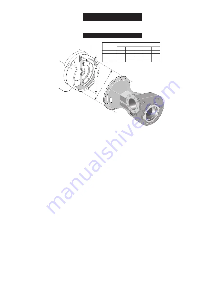
MATCHING PUMP END TO ENGINE
S.A.E. Bracket Size:
Type “B” engine drive pumps are available to fit engines
having a standard S.A.E. 5 through S.A.E. 1 flywheel housing.
For a new engine, the engine supplier can provide the S.A.E.
housing number.
For an existing engine, the flywheel housing bore and bolt
circle can be measured and compared against the standard
S.A.E. housing dimensions listed in Table I, to identify the
housing S.A.E. number.
• Measure the flywheel housing bore (A), and the bolt circle
(B), as accurately as possible with a tape measure (to the
nearest 1/32 inch).
• Count the number of threaded holes in the flywheel housing
(C). Test the threaded holes with a bolt, to determine the
thread series.
• Compare the measured dimensions (A), (B), and (C) against
Table I, to determine the S.A.E. number of the flywheel
housing, to be sure it matches the S.A.E. number of your
pump.
•
Record measurements on the dimension form on Page
23 in the spaces provided under Flywheel Housing
Dimension.
F00636
Page 5
General Information
Installation
ENGINE
A
B
C
Flywheel
Housing
Dimensions
20-1/8
20-7/8
12
7/16-14
17-5/8
18-3/8
12
3/8-16
16-1/8
16-7/8
12
3/8-16
14-1/4
15
12
3/8-16
12-3/8
13-1/8
8
3/8-16
A
B
C
1
2
3
4
5
S.A.E. Flywheel Housing Size
No.
Size
TABLE 1
Figure 2
Summary of Contents for S.A.E.
Page 28: ......