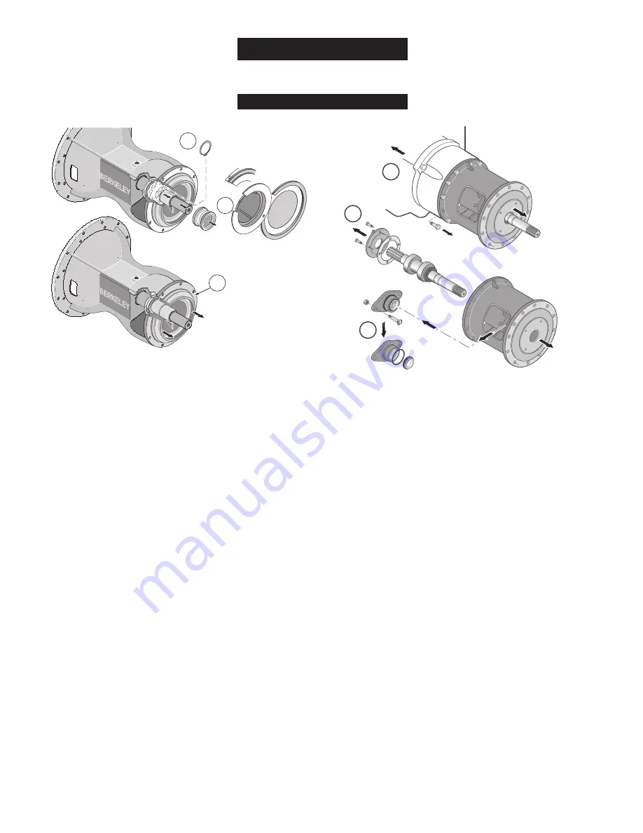
Berkeley S.A.E. Installation, Repair, And Operating Instructions Download Page 19

3.

If your pump has a bolted in balance ring, remove it; if it
has a pressed in balance ring, leave it in place unless
there isn’t room to get the seal out past it. If it doesn’t
have a balance ring, go to Step 4. 

Check the clearance between the balance ring and
the impeller hub. If it is more than .020” on a side,
replace the balance ring.

4.

Remove the seal retaining ring and pull the rotating part
of the seal off the shaft. 

Model B4EYQBHS

and similar pumps: See the special

section on this page. Others: go to Step 5.

5.

Z Series:

Pull the seal plate out until it clears the shaft,

bringing the stationary part of the seal out with it. Tap the
seal out of the seal plate and clean the seal cavity.

Other Pumps: Pull the stationary part of the seal out of
the cavity and clean the cavity.

6.

Install the new stationary seal in the seal cavity.

Apply a small amount of mineral oil to the O-Ring or
cup seat of the stationary seal.

Use the cardboard washer (supplied) and a piece of
pipe as a press; press the stationary seal into place.

Do not damage the seal face! 

7.

Reinstall the seal plate (if used) now. 

Cover all shaft threads with tape to protect the seal
during installation. 

Apply a small amount of mineral oil to the inside
diameter of the rubber ring in the rotating seal and to
the outside of the shaft sleeve. 

Slide the seal plate over the shaft now, taking care to
avoid damage to the stationary part of the shaft seal
as it goes over the shaft shoulder.

8.

After lubricating the rotating part of the seal, slide it onto
the shaft and sleeve until it seats against the stationary
(ceramic) part.

9.

Compress the seal spring on the shaft sleeve and
reinstall the seal retaining ring (if used).

10. Reinstall the balance ring (if used).

11. Slide or thread the impeller onto the shaft until it seats

solidly against the shaft shoulder, then install a new
impeller screw with its associated hardware.

12. Replace the volute. Use new gasket(s) and O-Ring(s).

B4EYQBHS and similar pumps (See Picture Above):

After STEP 4, you will need to:

A.

Remove the bracket from the engine. 

B.

Remove the outer bearing cap and slide the shaft
assembly back out of the bracket.

C.

Remove the seal retainer and tap out the stationary seal. 

D.

Clean the seal retainer and shaft (don’t scratch the
shaft!).

E.

Apply a small amount of mineral oil to the O-Ring or cup
seat of the stationary seal, to the inside diameter of the
rubber ring in the rotating seal, and to the outside of the
shaft sleeve.

F.

Use the cardboard washer (supplied) and a piece of pipe
to press the stationary seal into place.

G.

Inspect the oil seal and replace it if necessary. 

H.

Repack the bearings and reinstall the shaft in the bracket.

NOTE:

When the end of the shaft comes through the

front bearing bore in the bracket, slip the slinger and seal
retainer over the end of the shaft. BE SURE you don’t
damage the seal face on the shaft shoulder!

J.

Reinstall the outer bearing cap with a new gasket and
proceed to STEP 7 (“Reinstall the shaft sleeve....”)

F00636

Page 19

Seal/Impeller Replacement

Maintenance

1

3

2

Remove seal
plate

6056 0609

A

B

C

B4EY Series
Seal Chan

g

e

Se

q

uence

Summary of Contents for S.A.E.

Page 1: ...factory operation read these instructions before installing your new pump Should service be required this manual can be a valuable guide It should be kept near the installation for ready reference Rec...

Page 2: ...12 13 START UP Priming 14 15 Operation 15 MAINTENANCE General Information 16 Packing Ring Replacement 17 Impeller Removal 18 Seal Impeller Replacement 19 Shaft Maintenance Replacement 20 General Pump...

Page 3: ...Carefully read and follow all safety instructions in this manual and on pump Keep safety labels in good condition Replace missing or damaged safety labels General Safety Do not allow pump piping or a...

Page 4: ...ping to place excessive strain on the pump and may damage pump case Permanent Installation Pump and Engine should be set on a concrete foundation which is sufficiently substantial to absorb vibration...

Page 5: ...emperature increases When driving the pump at the RPM required to deliver water into the system piping the engine must operate within the engine manufacturers minimum and maximum RPM limits The power...

Page 6: ...onal analysis NOTE If the flywheel is fitted with a pilot bearing pressed into a bore at the center remove it to avoid interference with the pump shaft FLYWHEELS FOR INDUSTRIAL TYPE OVERCENTER CLUTCHE...

Page 7: ...81 2 44 2 94 7 B85401 1 3 8 10T 8 6 3 8 16 10 3 8 OD 9 62 4 81 2 44 2 94 7 B85402 1 1 2 10T 10 8 3 8 16 12 3 8 OD 11 62 4 47 2 13 2 75 7 B85403 1 3 8 10T 10 8 3 8 16 12 3 8 OD 11 62 4 47 2 13 2 75 7 B...

Page 8: ...gister fit on the flywheel Be sure to remove all preservatives from the engine s flywheel Fit the coupling into the flywheel Align the bolt holes and engage coupling with register fit on flywheel Tap...

Page 9: ...head will be a fraction of the published performance Threaded impellers may loosen F00636 Page 9 Verify Pump Rotation Installation DIESEL ENGINE Clockwise rotation View A looking toward fan View B lo...

Page 10: ...d to pump Straight run short as possible but at least 6 times pipe diameter D after elbow to stabilize flow All connections must be air tight NOTICE Companion Flange Kit Companion Flange Kit Companion...

Page 11: ...on hose that may collapse during operation due to insufficient strength No strainer may cause pump to clog Insufficient bottom clearance Vortex caused by insufficient submergence may cause pump to los...

Page 12: ...ld be full open during operation Maintain proper size throughout discharge system using as few elbows and tees as possible to keep friction loss to a minimum Install pressure gauge after reducer to ch...

Page 13: ...ocity before closing causing hydraulic shock water hammer Do not force pipe alignment that can cause flange stress F00636 Page 13 Discharge Connection Installation Not Recommended Do not use Gate Valv...

Page 14: ...th Suction Lift and Foot Valve Close air tight valve on discharge Remove pipe plug from highest opening on pump case Completely fill pump and suction piping with water Rotate shaft slowly allowing any...

Page 15: ...g during priming and that only the packing gland is used to control the flow of water the stuffing box during normal operation When necessary to replenish the grease supply use an NLGI No 4 Water Pump...

Page 16: ...r the bearings will be quite warm as high as 150 F which is normal If the surface temperature of the pump bracket or engine is excessive discontinue operation determine cause of temperature rise and c...

Page 17: ...stays on shaft Stagger ring joints 90 degrees apart Packing Rings Typical Packing Arrangement Pump liquid end removed for pictorial clarity only Remove packing gland and packing rings through frame cu...

Page 18: ...n the impeller NOTE Place the puller s fingers against the vanes in the impeller Pulling on the impeller s unsupported back shroud could easily break the impeller B Unscrew threaded impellers NOTE Pum...

Page 19: ...lder 8 After lubricating the rotating part of the seal slide it onto the shaft and sleeve until it seats against the stationary ceramic part 9 Compress the seal spring on the shaft sleeve and reinstal...

Page 20: ...16 Force enough grease into each bearing to fill internal space between the races Coat the bearing bores of bracket with oil Orient shaft assembly in the direction shown above Slide shaft and bearing...

Page 21: ...and shaft would be prudent WINTERIZING If pump is to be out of service for an extended period of time such as the winter months the following storage procedures should be followed Remove exterior dir...

Page 22: ...ng connections for leakage or possible misalignment Complete any lubrication requirements as dictated by pump and driver owner s manual Inspect packing or mechanical seal for possible replacement Exam...

Page 23: ...25 shows typical components used in the assembly of S A E mount centrifugal pumps Refer to these drawings when ordering any replacement parts MODEL S N OR DATE IMPELLER DIA BERKELEY PUMPS B M 788 0394...

Page 24: ...AE 2 12 Holes on 18 38 Bolt Circle SAE 3 12 Holes on 16 88 Bolt Circle SAE 4 12 Holes on 15 00 Bolt Circle SAE 5 8 Holes on 13 12 Bolt Circle Impeller Impeller Washer BERKELEY Outer Bearing Cap Pump S...

Page 25: ...609 Impeller Capscrew Shakeproof Lock Washer Impeller Washer SAE 4 12 Holes on 15 00 Bolt Circle SAE 5 8 Holes on 13 12 Bolt Circle L L L Use only water soluble grease in this fitting Clack Weight Rub...

Page 26: ...insufficient diameter for condition III SYSTEM A Pressure required by system at design Compare pump pressure and flow rate against pump characteristic curve flow rate exceeds pressure rating of pump...

Page 27: ...a three phase motor with single phase power through a phase converter will void the warranty Note also that three phase motors must be protected by three leg ambient compensated extra quick trip over...

Page 28: ......

Reviews: