Beretta Power Plus Box 150 Installation Manual Download Page 56


56

4  WATER IN CENTRAL HEATING 

SYSTEMS

INTRODUCTION

Water used in central heating systems MUST be suitably 

treated to ensure the correct functioning of those systems 

and to guarantee an extended working life for boilers and 

all other system components. This applies not only to exist-

ing systems but to newly installed systems too.

Sludge, lime-scale and pollutants present in the water can 

cause permanent damage to the heating unit, also within 

a short time and regardless of the quality standards of the 

materials used.

Contact the Technical Assistance Centre for any further in-

formation on type and use of additives.

Always conform to the standards and legislation ap-

plicable in the country of installation.

WATER IN CENTRAL HEATING SYSTEMS.
INSTRUCTIONS FOR THE DESIGN, INSTALLATION AND 
MANAGEMENT OF CENTRAL HEATING SYSTEMS.

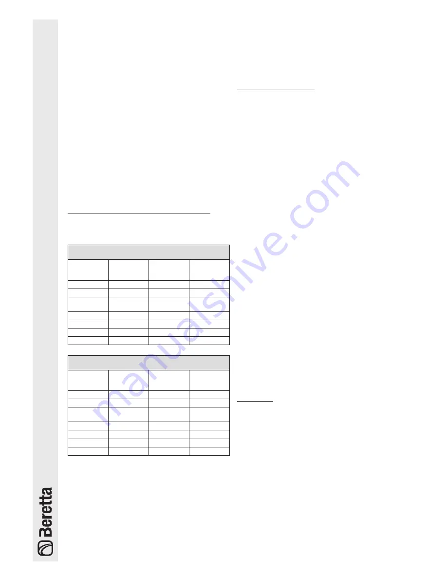
1. Chemical and physical characteristics of water

The chemical and physical characteristics of water used in 

central heating systems must conform to the requirements 

of EN 14868 standard and to the following tables:

STEEL BOILERS

with furnace power  < 150 kW

Initial filling 

water

Regular ser-

vice water  

(*)

ph

6-8

7,5-9,5

Hardness

°fH

< 10°

< 10°

Electrical 

conductivity

μs/cm

< 150

Chlorides

mg/l

< 20

Sulphides

mg/l

< 20

Nitrides

mg/l

< 20

Iron

mg/l

< 0,5

STEEL BOILERS

with furnace power  > 150 kW

Initial filling 

water

Regular ser-

vice water  

(*)

ph

6-8

7,5-9,5

Hardness

°fH

< 5°

< 5°

Electrical 

conductivity

μs/cm

< 100

Chlorides

mg/l

< 10

Sulphides

mg/l

< 10

Nitrides

mg/l

< 10

Iron

mg/l

< 0,5

(*) values for water in system after 8 weeks of functioning

General note on water used to top up systems:

-  If softened water is used to top up a system, 8 weeks 

of functioning after topping up, verify that the water in 

the system respects the above limits, in particular for 

electrical conductivity

-  This check is not necessary if demineralised water is 

used to top up the system.

2. Central heating systems

Do not use automatic filling devices to add water to 

central heating systems. Use a manual device in-

stead and record top-ups in the system service book.

If there are more than one boiler, they must all be put 

into service either contemporarily or with a very low 

rotation time during the initial period of service, so as 

to evenly distribute the limited quantity of initial lime-

scale.

A flushing cycle must be programmed after the plant 

has been installed to flush out any installation debris.

Water used to fill a system for the first time and water 

used to top it up must always be filtered (using syn-

thetic or metal mesh filters with a filtration rating of no 

less than 50 microns) to prevent sludge from forming 

and triggering deposit corrosion.

The heating system must be flushed out and cleaned 

with good workmanship before filling up the existing 

systems. The boiler may not be filled until after the 

heating system has been flushed out.

2.1 New central heating systems

The system must be filled up slowly the first time; once it is 

filled and the air expelled it should never need to be topped 

up again.

Systems should also be operated at maximum working 

temperature the first time they are started up, in order to 

facilitate de-aeration. (Gas is not released from the water at 

low temperatures).

2.2 Reconditioning old central heating systems

If a boiler has to be replaced, do not refill the entire cen-

tral heating circuit if the quality of water in it conforms to 

requirements. If the quality of water fails to conform to re-

quirements, either recondition the old water or separate the 

water circuits (water in the boiler circuit must conform to 

requirements).

3. Corrosion

3.1 Deposit corrosion

Under-deposit corrosion is an electrochemical process, 

due to the presence of sand, rust, etc., inside the mass 

of water. These solid substances generally deposit on the 

bottom of the boiler (sludge), on tube and pipe heads or in 

the gaps between pipes and tubes.

Micro-corrosion phenomena may be triggered off owing 

to the difference in electrochemical potential coming to be 

created between the material in contact with the impurity 

and the surrounding one.

Summary of Contents for Power Plus Box 150

Page 1: ...Installation Manual THERMAL MODULES CONDENSING Power Plus Box Installation Manual EN...

Page 2: ...r condensing systems comply with Directive 2009 142 EC Gas Appliances Directive 92 42 EEC on efficiency requirements and Annex E and Pres Republic Decree n 412 26 Au gust 1993 Electromagnetic Compatib...

Page 3: ...ensions and weights 23 2 4 Handling 24 2 5 Installation premises 24 2 6 Installation in older systems and systems requiring modernisation 24 2 7 Water connections 25 2 8 Flue gas evacuation for instal...

Page 4: ...Centre B 1 2 Precautions The operation of any appliance that uses fuel electrical power and water demands that a number of fundamental safety precautions be respected a Do not allow children or infirm...

Page 5: ...uation and condensate outlet mani folds can have an outlet to the left or to the right Power Plus Box 150 Base module consisting of 3 heat generators for heating and DHW production systems Heat input...

Page 6: ...ima di installare e mettere in servizio l apparecchio Laterale DX Temperatura ambiente min 10 C max 50 C Questo apparecchio pu essere installato e funzionare all aperto o solo in locali permanentement...

Page 7: ...ld 9 System return manifold 10 Single heating element flue gas analysis outlet 11 Fan 12 Single heating element flue gas exhaust union 13 Automatic bleed valve 14 Safety thermostat 15 Drain cock 16 Ma...

Page 8: ...R PLUS BOX 200 POWER PLUS BOX 200 POWER PLUS BOX 150 SZ1 Delivery manifold sensor SZ2 Low system temperature sensor SB Boiler sensor SE Outdoor sensor PZ1 Zone 1 circulator high temperature PZ2 Zone 2...

Page 9: ...Tm 50 C 60 C 40 C 106 6 Chimney loss with burner operating 1 3 Chimney loss with burner off 0 1 Casing loss Tm 70 C 0 5 Flue gas temperature Return temperature 5 C C CO2 at minimum 9 0 G20 10 4 G30 3...

Page 10: ...re rating P1 48 9 65 1 kW EFFICIENCY at rated thermal input and at high temperature rating 4 88 4 88 4 at 30 of rated thermal input and at low temperature rating 1 97 8 97 8 ADDITIONAL ENERGY CONSUMPT...

Page 11: ...ater and minimum pressure switch 7 Circulator or 2 way valve 8 Gas valve 9 Flue gas exhaust union with check valve and flue gas analysis outlet 10 Manual diverting valve 11 Return shut off valve 12 Ga...

Page 12: ...P available for system circulation 1 heating element Circulator characteristic curve Heating element pressure drop at 2000 l h 550 mbar Flow rate necessary for every heating element 2000 l h b At the...

Page 13: ...8 18 61568 1 26135 20 12090 39 6033 58 3216 77 1817 96 1079 17 58719 2 25044 21 11634 40 5828 59 3116 78 1766 97 1051 16 56016 3 24004 22 11199 41 5630 60 3021 79 1717 98 1024 15 53452 4 23014 23 1078...

Page 14: ...J2 J8 J10 R4 2 3 J3 J6 J5 J7 F1 Fuse 3 15 A 1 R6 R5 MC R3 R2 On Valv Mix Alarm Comune J12 2 BUS J14 1 R1 4 3 T1 Ebus contr remoto 24V contr remoto Comune Analogic Input Comune T A circ 1 Comune T A c...

Page 15: ...entaz Sens Hall Soffiante Input Sens Hall Soffiante Comune Sens Hall Termostato limite Valvola gas 2 1 3 a 9 m J16 NTC fumi J9 J4 a 10 WD J5 T3 PC Main SLAVE 3 IG3 C TS VG SM SR SF EA ER J10 J17 a m 1...

Page 16: ...that can be deactivated automatically ON in case of permanent errors 6 Single heating element slave reset button 7 Instrument panel 8 FOURTH heating element switch only for Power Plus Box 200 9 THIRD...

Page 17: ...er is shut off is 6 minutes When the last burner is turned off the circulator only stops when the room thermostat demand stops The ignition shut off control function in both cascad ing management mode...

Page 18: ...es and operating status of the various circuits Press the button to scroll forward and view the values set for the individual circuits The values listed below will be displayed in succession by pressi...

Page 19: ...he desired value e g 40 C 5 Press OK to memorize the new value 6 After 3 secs the display will return to the display mode with the new setpoint If there is no change after pressing Set esc for 10 secs...

Page 20: ...and change the user and installer parameters Procedure for accessing the programming mode POS PROCEDURE DISPLAY 1 Manifold delivery temperature T1 e g T1 80 C 2 Press Set esc and OK After 5s the secon...

Page 21: ...identifying the errors POS PROCEDURE DISPLAY 1 The display starts to flash to indicate one or more errors 1 b Press the address of the first unit will appear on the display alternating with the first...

Page 22: ...anty certificate Barcode labels 6 Accessory envelope containing Natural gas to LPG transformation kit valid for Eu rope Door key The following is also supplied positioned on the base inside the modula...

Page 23: ...5 RI 1530 MI GAS SC SF RI MI GAS DESCRIPTION Power Plus Box 150 200 MI System delivery manifold 5 DN 125 PN 6 DN RI System return manifold 5 DN 125 PN 6 DN GAS Gas manifold 3 DN 80 PN 6 DN SF Flue Man...

Page 24: ...collecting condensate and for flue gas exhaust see the specific chapter Flue gas evacuation for installations in central heating plants b Take into consideration the space that is required in order t...

Page 25: ...hydraulic separator near the system s delivery and return manifolds To make it easier to position the modular system in the area of installation refer to the Handling paragraph Adjust the feet of the...

Page 26: ...tinguishing polypropylene class B1 implemented with pipes with socketed connections or equivalent lines The maximum equivalent length of the flue gas evacuation lines is indicated in the table Each mo...

Page 27: ...1 1 b If installing in a central heating plant it is recommended to direct both the products deriving from the boiler con densate outlet as well as the condensate deriving from the flue gas manifold...

Page 28: ...t at least for one heating season in the case of maximum formulation of condensate The operation can be checked easily using the pH indica tor cards available commercially They can be purchased from a...

Page 29: ...diagram on the following page referring to the wiring diagrams Provide a three pole cable 8 to supply the 230V 50Hz line direct it through the hole made in the casing of the electric panel and connect...

Page 30: ...Respect the connection L line N neutral Keep the earth conductor 2 cm longer than the power supply conductors Use cables with a section greater than or equal to 1 5 mm2 complete with cable terminal ca...

Page 31: ...ement and adjust parameter 39 to make any necessary correction b The connection cable between the outdoor sen sor and the control panel must not have couplings If these are necessary they must be wate...

Page 32: ...o or three turns 3 Open the filling tap 4 provided on the system until the pressure indicated on the pressure gauge is 1 5 bar Close the filling tap 4 4 b Deareation of the Power Plus Box modular syst...

Page 33: ...rtant to first check that the heating system shut off and gas taps are open the type of gas and the supply pressure comply with the features of the modular system the hydraulic circuit pressure when c...

Page 34: ...rom the second modular system on wards To do so see the paragraph Setting addresses for cascade coupling If there is a low temperature system set parameter 34 1 4 8 7 2 6 3 1 5 Adjust the room thermos...

Page 35: ...ight will flash To change this value press or To confirm press OK The system will turn on in DHW mode until the demand is satisfied When the modular system is in stand by the Master unit display will...

Page 36: ...nerate a high temperature heating demand at maximum power Proceed as follows press the Set esc and buttons at the same time for 5 seconds generate the heat demand using the room thermo stat The system...

Page 37: ...ith G20 natural gas with a flue gas exhaust line with L 15m parameter 36 01 b All checks must be performed by Technical Assis tance Centre 3 3 Adjusting the functional parameters The heating functions...

Page 38: ...20 CLIMATIC CURVE HIGH TEMPERATURE circuit T_CH_High Max heat requirement T_CH_High_foot T_out_min 2 Setpoint_T_CH_Low Low temperature circuit setpoint parameter 3 If the fixed point operating mode is...

Page 39: ...There are 2 cases Fixed point operation Par 14 0 Operation with climatic control Par 14 1 FIXED POINT OPERATION PAR 14 0 With the high temperature circuit attenuation disabled Par21 0 when the high t...

Page 40: ...he setpoint is calculated based on the outdoor temperature If the outdoor temperature Tout_min Par 37 preset to 0 C then setpoint setpoint_T_Ch_low If the outdoor temperature Tout_max Par 38 preset to...

Page 41: ...prevents burner ignition and shut off in the case of a low heat demand The conditions for low load operation activation is controlled in every Slave card that sends the function activation request to...

Page 42: ...Voltage Volt 0 1 2 3 4 5 6 7 8 9 10 Fig 2 The burner ignited when Delivery temp Setpoint_ch_high Par 1 Ch_high_ hist_on Par 19 Delivery temp Setpoint_ch_low Par 3 Ch_low_ hist_on Par 26 The burner sh...

Page 43: ...nit goes below 0 5 bar 3 7 Setting addresses for cascade coupling If it is necessary to implement multiple modular systems with a cascading connection the second modular system on wards must be discon...

Page 44: ...must not be changed 1 2 3 4 OFF ON Master Slave Slave Slave Master Slave Slave Slave FIRST modular system SECOND modular system BLOCK 1 BLOCK 2 J14 Slave 1 2 3 4 OFF ON Address for BLOCK 1 Address for...

Page 45: ...laves not present Check that the bipolar switches of the individual units are ON Check the addresses on the slave Check the slave BUS connection Replace the Master card Replace the Slave card E34 42 I...

Page 46: ...as pressed more than 7 times in 30 min Wait for the error to disappear If the error did not disappear after max 40 min replace the Slave card E35 35 Water differential pressure switch error contact op...

Page 47: ...tpoint of power supplied in hot water mode 8 h w max T 60 C 10 C 80 C Max value hot water setpoint 9 h w Priority 0 0 2 Hot water system priority 0 1 Hot water functioning with heating until reaching...

Page 48: ...Mixer valve stand by differential 33 Power control 1 0 1 0 power distributed over min number burners 1 power distributed over max number burners 34 Pump mode 0 0 1 Third pump setpoint 0 Main pump of s...

Page 49: ...em and remove the one for G20 remove the gas label from the outside Gruppo termico regolato per G30 G31 28 30 37 mbar Paese di destinazione Paese di destinazione Tipo di apparecchio Caldaia categoria...

Page 50: ...refully retighten the cap 1 3 12 Temporary shutdown In the case of temporary absences weekends short trips etc proceed as follows set the room thermostats to approx 10 C set parameter 2 to 10 or adjus...

Page 51: ...Do not use fuels sponges impregnated with abrasive solutions or powder detergents INSIDE Before starting internal cleaning operations close the gas shut off valves close the system taps Access to the...

Page 52: ...10 11 12 13 Once the maintenance operations are complete refit the components working in the opposite direction of what was described Disassembling the circulator open the two front doors in the casi...

Page 53: ...on of the electrode and replace it if necessary 22 17 21 23 Once the maintenance operations are complete refit the components working in the opposite direction of what was described b Check that the g...

Page 54: ...t upon con sent of the modular system control Gas valve Check for the presence of 230Vac voltage on the gas valve terminals check wiring and connections The modular system does not start No electric p...

Page 55: ...circulator Check the electrical connection of the circulator Frequent tripping of the system safety valve System safety valve Check calibration or efficiency System circuit pressure Check the circuit...

Page 56: ...to add water to central heating systems Use a manual device in stead and record top ups in the system service book b If there are more than one boiler they must all be put into service either contemp...

Page 57: ...is therefore important to avoid two factors possibly leading to the above mentioned pro cesses i e contact between air and water in the installation and regular topping up with fresh water To elimina...

Page 58: ...transmitted by ISPESL memorandum no 102 99 dated 13 12 99 taking into account the positive results of the checks and tests carried out at the manufacturer s laboratory we believe that multiple elemen...

Page 59: ...59...

Page 60: ...oilers com Beretta reserves the right to modify the characteristics and specifications given in this publication at any time and without prior notice as part of its policy of continuous product improv...

Reviews: