Benewake CE30-D Operation Manual Download Page 6

Benewake(Beijing)Co., Ltd

CE30-D Product Manual - V04

Page

6

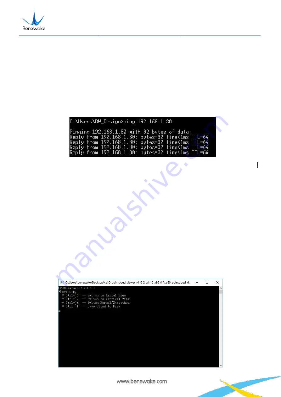
If it prompts as shown in Figure 6, it indicates that the LiDAR is working normally with the data connection
available. If no, it indicates that the data link suffers from ping failures. Please check as follows:

a) Check whether the indicators light up on the front panel of the LiDAR and whether the red lamp keeps

normally on and flashing after startup;

b) Check whether the power supply is available and whether the voltage is 12V with the rated current ≥ 3A;
c) Check whether the computer network port is normally connected and whether the local Ethernet is

identified;

d) Disconnect the power supply and wait for 5 seconds before reconnecting it.

Figure 5 Data connection check

2.2 Display program window

Double click the program

ce30_pointcloud_viewer.exe

to open the display program and the prompt and

point cloud image windows will appear as illustrated in Figure 6 for LiDAR version and operation shortcuts.

The prompt window is used to display the LiDAR connection, shortcut prompts and other running
information.

The point cloud image window displays the point cloud images in the LiDAR field of view calculated based
on the depth map and projection relation. In this window, hold down the left mouse button and move the
mouse to change the direction for viewing the point cloud images; use the mouse wheel and you can zoom
in/out the point cloud image; hold down the mouse wheel and move the mouse to move the point cloud
image horizontally.

Summary of Contents for CE30-D

Page 1: ...CE30 D Solid State Array LiDAR Operation Manual Page 1...

Page 2: ...ina Copyright The Copyright of this document is protected All the rights involved herein belong to Benewake Beijing Co Ltd Any copy activity of this document no matter in whole or in part should be in...

Page 3: ...uction 7 5 Line sequence descriptions 8 6 Installation diagram 8 7 Test Instruction and Description 9 7 1 Detecting Range Description 9 7 1 1 Blind Zone 9 7 1 2 Detecting Range 9 7 2 Vertical Angle Re...

Page 4: ...e of M3 1 Enclosure 2 Emitting panel working area cannot be covered 3 Reception panel working area cannot be covered 4 Power 5 Ethernet interface M8 aerial plug 6 Equipment installation hole M3 Figure...

Page 5: ...DAR with the aerial plug cables as illustrated in Figure 3 connect the power interface to the adapter DC 12V 3A DC 5 5 2 5mm connect the aerial plug network port RJ45 to the computer b Set the Etherne...

Page 6: ...ply and wait for 5 seconds before reconnecting it Figure 5 Data connection check 2 2 Display program window Double click the program ce30_pointcloud_viewer exe to open the display program and the prom...

Page 7: ...the Windows interface 3 Coordinate transformation The CE30 D outputs distance and angle by polar coordinates In order to facilitate the reconstruction and application of 3D point cloud image they can...

Page 8: ...on abnormal I2C etc 5 Line sequence descriptions Figure 9 Line sequence at the power supply port red power positive black power negative Note 1 The current should be more than 3A for the power adapter...

Page 9: ...a blind zone as shown in Figure 11 would appear This is caused by the overexposure when objects reflected light is excessive LiDAR will filter the data from this overexposure zone When the detected o...

Page 10: ...the vertical angle resolution is 0 2 degree so that CE30 D has more precise resolution capacity The detection angle in vertical direction is presented in Table 1 Table 1 Detecting angle in vertical di...

Page 11: ...acy within 7m are at the same level The detecting performance with different reflectivities are within expectation The outdoor accuracy at long range is slightly poor as shown in the above figure 3 Th...

Page 12: ...Optical Path Based on ToF LiDAR principle if there are multiple echo regions as shown in the figure below at the working height of the radar the multi path phenomenon will be triggered the LiDAR recei...

Page 13: ...he object onto the sensor of the LiDAR If some pixels receive signals from both front and rear obstacles at the same time the output distance of this pixel may be the value between the two obstacles T...

Page 14: ...supply is DC 12V 0 5V 3A and power consumption is 8w So how much is the working current A2 The normal working current is lower than 0 65A when radar working normally There will be relatively high pul...

Reviews: