8
The configuration should meet the requirements for the ve
-
locity of compressed air.
The pressure drop of the pipeline must exceed the set
pressure by 5% or more.
Use the minimum amount of bends to ensure the
smoothest airflow as possible. If the pipeline run is long,
the diameter of the pipe should be increased.
Prevent any condensation from flowing into any
equipment by installing the pipeline run with a minimum
slope of 1-2˚ with drain valves located at the low spots.
Slope piping so that it drains towards a drop leg or
moisture trap away from the compressor.
Consideration of future emergencies, temporary
compressor and maintenance needs of equipment should
be incorporated into the pipeline design and may include
bypass lines, shut off valves, air take off locations, strain
on the piping due to dead weight of the pipe, expansion
and contraction of the pipe, strains for internal pressure.
An air oil separator should be installed at the head of the
pipeline.
A one way valve is mounted on the exit line of the
compressor.
The compressor has integrated anti vibration devices and
does not have any support for the air pipeline. All
external piping requires approved support systems. All
piping should be connected to the compressor out line in
such a manner as to keep any condensation from running
back towards the compressor.
When an air drier is installed in the pipeline, an air tank/
reservoir is recommended as the compressed air
temperature will be lowered prior to entering the dry-
ing system and therefore increase the efficien
-
cy and lower the energy use of the drying system.
A flexible hose or coupling should be installed between
the compressor and the service piping/ and or the tank;
and the tank and the service piping.
Failure to properly install the tank can lead to cracks at
the welded joints and possible bursting.
SECTION 6
FLOOR MOUNTING
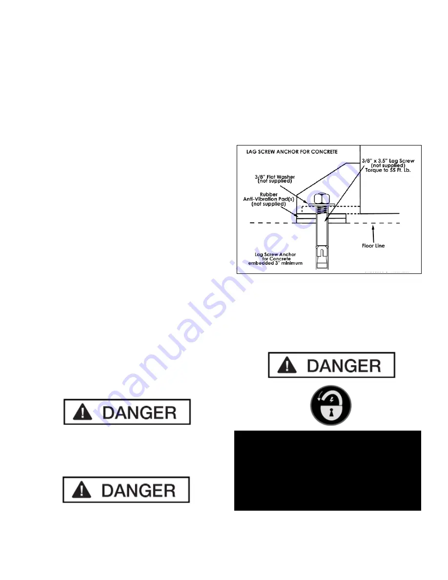
The compressor should be bolted onto a flat, even,
concrete floor or on a separate concrete foundation.
If installing the optional Air Tank, Anti-vibration pads
should be used between the tank legs and the floor.
When using anti-vibration pads, do not draw bolts tight.
Allow the pads to absorb vibrations. (See Fig. 6.1)
SECTION 7
ELECTRICAL CONNECTIONS
Fig. 6.1
DO NOT PERFORM ANY MAINTENANCE OR
INSTALLATION OF ANY COMPONENTS
WITHOUT FIRST ENSURING THAT ELECTRICAL
POWER HAS BEEN DISCONNECTED AT
THE SOURCE OR PANEL AND CANNOT BE
RE-ENERGIZED UNTIL ALL
MAINTENANCE AND/OR INSTALLATION
PROCEDURES ARE COMPLETED.
Summary of Contents for RS7580H603
Page 34: ...34 Frequent ...
Page 35: ...35 ...
Page 36: ...36 RS7580H603 SCREW COMPRESSOR PARTS LIST ...
Page 37: ...37 RS7580H603 SCREW COMPRESSOR PARTS LIST ...
Page 38: ...38 RS7580H603 SCREW COMPRESSOR PARTS LIST ...
Page 40: ...40 RS7580H603 SCREW COMPRESSOR PARTS LIST ...
Page 41: ...41 RS7580H603 SCREW COMPRESSOR PARTS LIST ...
Page 42: ...42 RS7580H603 COMPRESSOR ELECTRIC DIAGRAM ...
Page 43: ...43 RS7580H603 COMPRESSOR ELECTRIC DIAGRAM ...
Page 44: ...44 RS7580H603 COMPRESSOR ELECTRIC DIAGRAM ...
Page 45: ...45 ...
Page 48: ......


