background image

12

STEP 5

(Connecting Air Supply)

Refer to page 18 if installing with the Optional Rolling 
Bridge Jack Airline Kit.

1.  Remove the thread protector from the air inlet of the 
Pump. Select and install the threaded 

fi

 ttings (not 

supplied) which are compatible with your air supply 

fi

 ttings. The air supply should be 20 CFM / 57 M3/MIN) 

and 100 PSI  (7 BAR) to obtain the rated hydraulic pressure.  
Air Supply should be regulated to a maximum of 125 PSI (8.6 
BAR)  (See Fig. 5.1)

2.  An appropriate air line regulator, water separator and 
lubricator should be installed on the Air Supply line. The 
absence of these items will void the warranty on pneumatic 
components. (See Fig. 5.2)
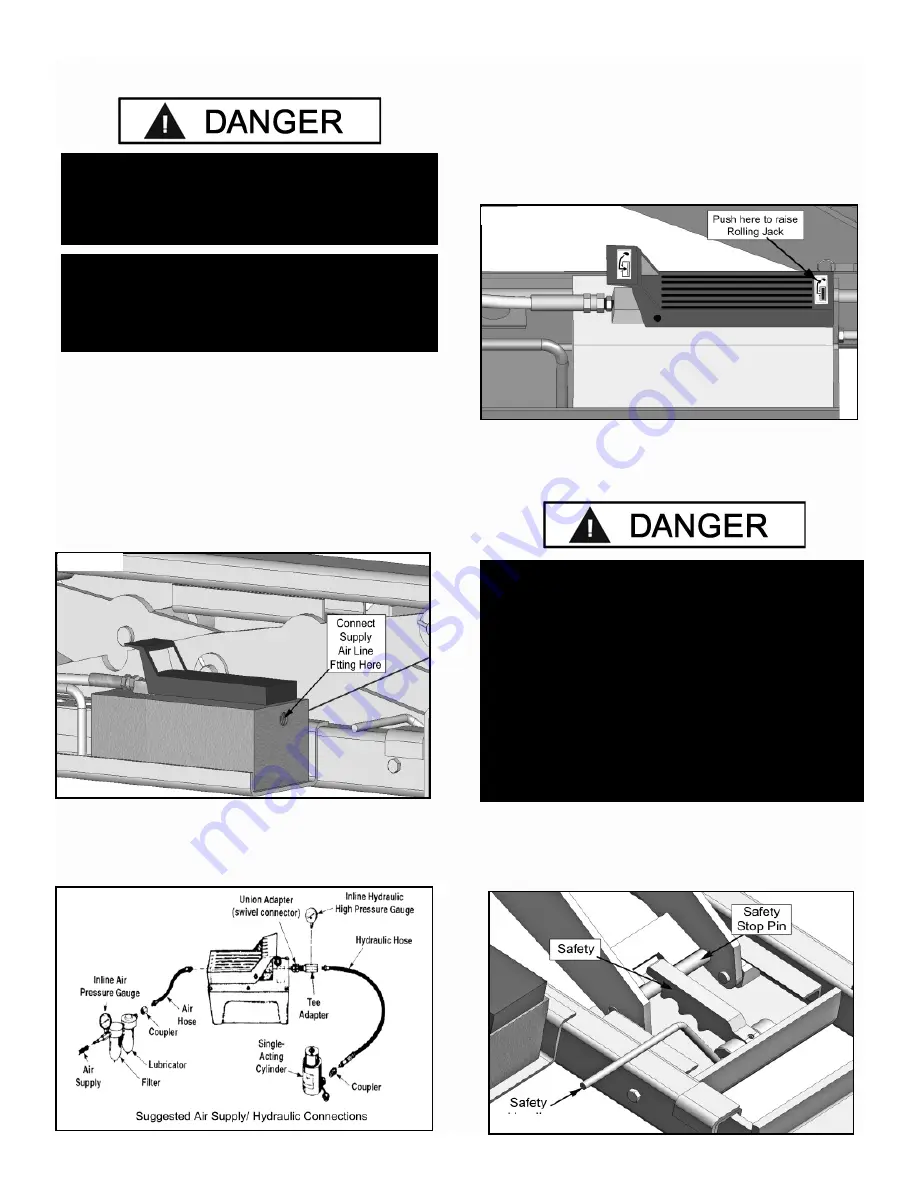
STEP 6

(Start Up / Final Adjustments)

1.  Raise the Jack 

WITHOUT

 a vehicle to check for proper 

operation of the Rolling Bridge Jack.

2.  Depress the Pedal on the lifting end to raise the Jack 
through the full range of the Jack. (See Fig. 6.1)

Under certain circumstances it may be necessary to prime 
the Air Hydraulic Pump Unit. Refer to the manual that came 
with the pump for these instructions.

3.   Lower the Jack onto the nearest Safety Stop Pin. When 
the Jack is loaded with a vehicle make sure the Jack is 
resting on the Safety Stop Pin prior to performing any work 
on the vehicle. (See Fig. 6.2)

DANGER!

THE AIR SUPPLY SHOULD BE TO 

20 CFM (.57 M3/MIN.) AND 100 PSI  (7 BAR).  

 AIR SUPPLY SHOULD BE REGULATED TO A

 MAXIMUM OF 125 PSI (8.6 BAR)

DANGER!

DISCONNECT AND / OR RELEASE THE PRESSURE 

FROM THE AIR SUPPLY SYSTEM / HOSES BEFORE 

PERFORMING ANY INSTALLATION OR MAINTENANCE 

OF THE AIR SUPPLY SYSTEM.

DANGER!

VISUALLY CONFIRM THAT ALL PRIMARY
SAFETY LOCKS ARE ENGAGED BEFORE

ENTERING WORK AREA.

Suspension components used on this Jack are

intended to raise and lower the Jack only and are not 
meant to be load holding devices. Remain clear of 
elevated Jack unless visual confirmation is made that 

all primary Safety Locks are fully engaged and 

the lift is LOWERED onto the Safety Locks. 

Refer to installation /operation manual for proper 

Safety Lock procedures and /or further instruction.

Fig. 5.1

Fig. 5.2

Fig. 6.1

Fig. 6.2

Summary of Contents for RJ-12

Page 1: ...without reading this manual and the important safety instructions shown inside 1645 Lemonwood Dr Santa Paula CA 93060 USA Toll Free 1 800 253 2363 Tel 1 805 933 9970 Fax 1 805 933 9160 www bendpak com...

Page 2: ...2 This page intentionally left blank...

Page 3: ...ormal use BendPak Inc shall repair or replace at their option for the warranty period those parts returned to the factory freight prepaid which prove upon inspection to be defective BendPak Inc will p...

Page 4: ...e lift for correct initial function Read and follow the safety instructions Keep them readily available for machine operators Make certain all operators are properly trained know how to safely and cor...

Page 5: ...ction 7 Safety Warning Instructions 7 Tools Required 8 Step 1 Verifying Lift Installation 8 Step 2 Rolling Bridge Jack Capacities 8 Step 3 Adjusting Lift Jack Orientation 9 10 Step 4 Installing Jack o...

Page 6: ...rior to installation Do not operate this machine until you read and understand all the dangers warnings and cautions in this manual For additional copies or further information contact BendPak Inc Ran...

Page 7: ...ined personnel come in contact with or operate lift 6 USE LIFT CORRECTLY Use lift in the proper manner Never use lifting adapters other than what is approved by the manufacturer 7 DO NOT override self...

Page 8: ...bodily harm and void product warranty Manufacturer will assume no liability for loss or damage of any kind expressed or implied resulting from improper installation or use of this product PLEASE READ...

Page 9: ...hop crane you may need to lock the lift on the first Safety Lock to make room for the legs of the Shop Crane 2 If adjustable adjust the Runway of the lift to the desired width Be sure to check the spe...

Page 10: ...10 Fig 3 2...

Page 11: ...e process for the other Rolling Bridge Jack if installing in pairs 8 Raise the lift up off the ground so that the Rolling Bridge Jack is off the ground and lower the lift onto the first safety stop EN...

Page 12: ...e necessary to prime the Air Hydraulic Pump Unit Refer to the manual that came with the pump for these instructions 3 Lower the Jack onto the nearest Safety Stop Pin When the Jack is loaded with a veh...

Page 13: ...in position 4 Before raising vehicle be sure all personnel are clear of the lift and surrounding area Pay careful attention to overhead clearances Determine the proper lift points on the vehicle by re...

Page 14: ...e the Safety off the Safety Lock Pin See Fig 7 3 4 Push the Lowering side of the Pedal on the Air Hydraulic Pump until the lift has descended completely When lowering the lift PAY CAREFUL ATTENTION th...

Page 15: ...7 6 2 Check Safety Locks to insure they are in good operating condition 3 Make a visual inspection of ALL MOVING PARTS and check for excessive signs of wear 4 Replace ALL FAULTY PARTS before lift is...

Page 16: ...16...

Page 17: ...an The vehicle manufacturer s recommendations should be used for spotting and lifting the vehicle LIFT OPERATION SAFETY It is important that you know the load limit Be careful that you do not overload...

Page 18: ...dures before operating lift KEEP HANDS AND FEET CLEAR Remove hands and feet from any moving parts Keep feet clear of lift when lowering Avoid pinch points ONLY TRAINED OPERATORS should operate this li...

Page 19: ...he integrated air line kit may have been an optional modification on some lift models Contact BendPak technical support for assistance if adding Rolling Jacks Air Line Kit after purchase Optional Inte...

Page 20: ...20...

Page 21: ...HHB 3 8 16 x 2 1 4 1 16 5545130 WASHER 3 8 SL 1 17 5530738 HHB M10 x 1 5 x 25 4 18 5530054 SSS M10x1 5x12 1 19 5530055 SSS M6x1x10 2 20 5535013 NUT M10 x 1 5 NL 4 21 5540109 E RING 16mm OD DIN 6799 0...

Page 22: ...x 25 4 15 5530055 SSS M6x1x10 2 16 5530054 SSS M10x1 5x12 1 17 5540109 E RING 16mm OD DIN 6799 0160 4 18 5545130 WASHER 3 8 SL 1 19 5550100 FTG 3 8 NPT 04 JIC 1 20 5550086 1 21 5530132 HHB 3 8 16 x 2...

Page 23: ...SHER 3 8 SL 1 16 5530738 HHB M10 x 1 5 x 25 4 17 5535998 NUT M10 x 1 5 4 18 5550086 FTG ELB 04 NPT x 04 JIC 1 19 5585120 AIR HYDRAULIC PUMP 1 20 5550100 FTG 3 8 NPT 04 JIC 1 21 5540109 E RING 16mm OD...

Page 24: ...4 A 16 5505136 SPRING PIN M5 x 40 4 17 5530738 HHB M10 x 1 5 x 25 4 18 5535998 NUT M10 x 1 5 4 19 5530191 HHB 3 8 16 x 2 3 4 1 A 20 5545130 WASHER 3 8 SL 1 A 21 5530054 SSS M10x1 5x12 5 22 5585120 AIR...

Page 25: ...SPRING PIN M6 x 50 4 17 5545130 WASHER 3 8 SL 1 A 18 5530133 HHB 3 8 16 x 3 1 A 19 5530054 SSS M10x1 5x12 5 20 5585120 AIR HYDRAULIC PUMP 1 21 5550086 FTG ELB 04 NPT x 04 JIC 1 22 5550100 FTG 3 8 NPT...

Page 26: ...JECTION TM 01 31 2010 SEE SHIPPING INSTRUCTIONS FOR FINAL PACKAGING 1 DIMENSIONS ARE IN MM 2 1 3 REVISION REV DESCRIPTION DATE EDITED BY ECO A PRODUCTION RELEASE 01 05 2010 AC 00167 NEXT ASSEMBLY 5260...

Page 27: ...APTER RETAINER PIN 2 A SHEET 1 OF 1 REV DWG NO A SIZE TITLE NAME DATE CHECKED DRAWN SIZE MATERIAL A 1645 LEMONWOOD DR SANTA PAULA CA 93060 PROPRIETARY AND CONFIDENTIAL THE INFORMATION CONTAINED IN THI...

Page 28: ...arts Or Service Contact BendPak Inc Ranger Products 1645 Lemonwood Dr Santa Paula CA 93060 Tel 1 805 933 9970 Toll Free 1 800 253 2363 Fax 1 805 933 9160 www bendpak com www rangerproducts com p n 590...

Reviews: