background image


1645 Lemonwood Dr. 

Santa Paula, CA, 93060  USA 

Toll Free: (800) 253-2363 

Tel: (805) 933-9970 

bendpak.com


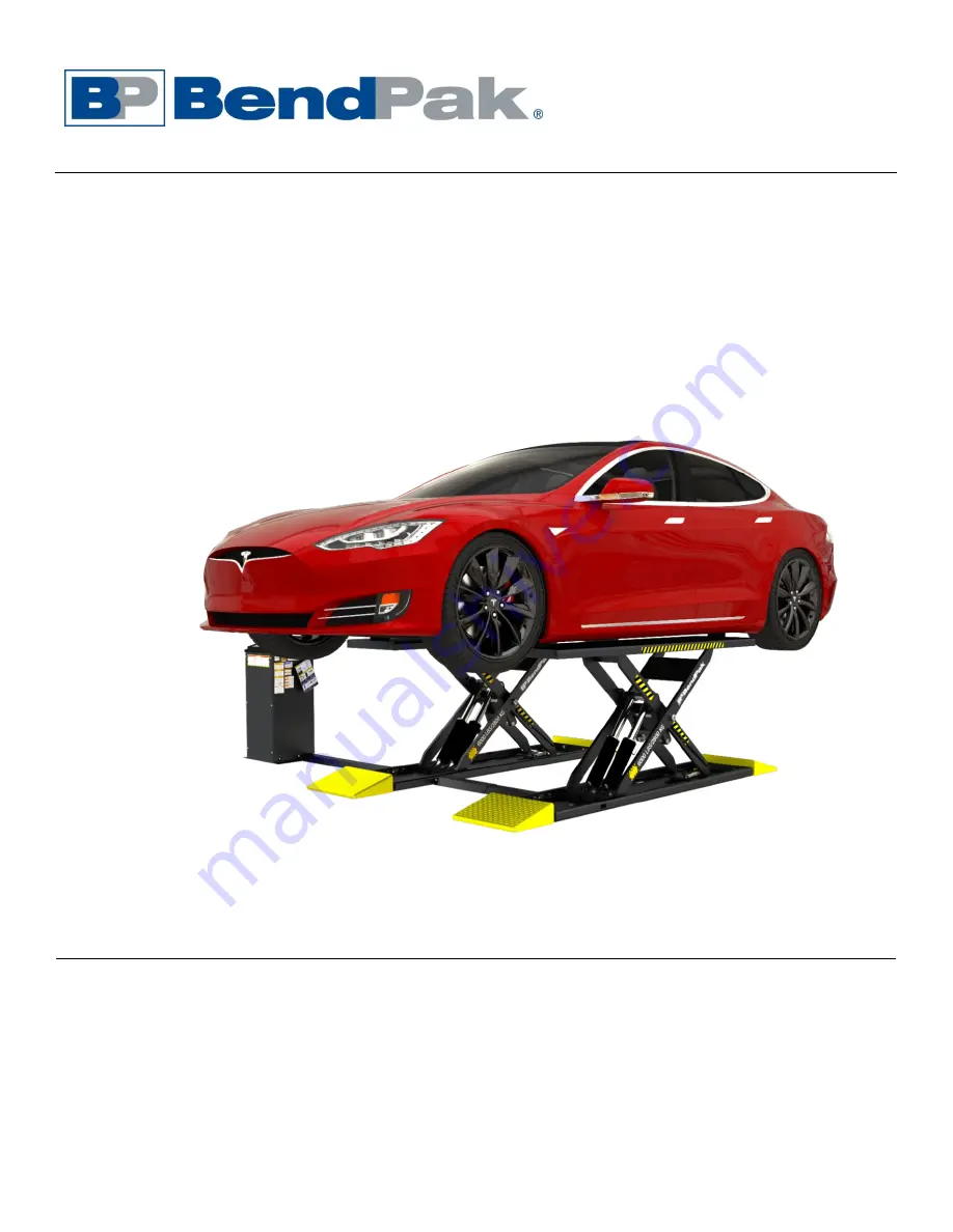
Mid-Rise Scissor Lift 

Installation and Operation Manual


Manual P/N 5900030 — Manual Revision D — April 2021 


Models

:      • MDS-6EXT        • MDS-6EXTF        • MDS-6LP        • MDS-6LPF 


Model MDS-6EXT shown. 


Designed and engineered by BendPak Inc. in Southern California, USA. Made in China. 


DANGER


Read the 

entire contents

 of this manual 

before

 using this 

product. Failure to follow the instructions and safety precautions in 
this manual can result in serious injury or death. Make sure all other 
operators also read this manual. Keep the manual near the product 
for future reference.


By proceeding with setup and operation, 

you agree that you fully understand the contents of this 
manual and assume full responsibility of product use

.


Summary of Contents for MDS-6EXT

Page 1: ...BendPak Inc in Southern California USA Made in China DANGER Read the entire contents of this manual before using this product Failure to follow the instructions and safety precautions in this manual can result in serious injury or death Make sure all other operators also read this manual Keep the manual near the product for future reference By proceeding with setup and operation you agree that you...

Page 2: ...m support warranty for full warranty details Go to bendpak com support register your product and fill out the online form to register your product be sure to click Submit Safety Your new product was designed and manufactured with safety in mind Your safety also depends on proper training and thoughtful operation Do not set up operate maintain or repair the unit without reading and understanding th...

Page 3: ... users of the MDS 6EXT F and MDS 6LP F models including anyone who sets up operates maintains or repairs them DANGER Be very careful when setting up operating maintaining or repairing this equipment failure to do so could result in property damage product damage injury or in very rare cases death Make sure only authorized personnel operate this equipment All repairs must be performed by an authori...

Page 4: ... of lading freight bill invoice and photographs Our willingness to assist in helping you process your claim does not make us responsible for collection of claims or replacement of lost or damaged materials Safety Considerations Read this manual carefully before using your new product Do not set up or operate the product until all installers operators are familiar with all operating instructions an...

Page 5: ...roperty damage NOTICE Calls attention to a situation that if not avoided could result in product or property damage Tip Calls attention to information that can help you use your product better Liability Information BendPak Inc assumes no liability for damages resulting from Use of the product for purposes other than those described in this manual Modifications to the equipment without prior writte...

Page 6: ... straight onto the Platforms without having to go up a Ramp the tops of the Platforms are flush with the floor Q Can the Lifts covered in this manual be installed outdoors A No All Lifts detailed here are approved for indoor installation and use only Outdoor installation is prohibited Q Can I put the Console on either side of the Lift A Yes The Hydraulic Hoses and the Covers that come with the Lif...

Page 7: ...t with the lifting points on the underside of the Vehicle being raised Eight tall and eight medium Lift Blocks are included Base The bottoms of the Lift They hold the Hydraulic Cylinders the Scissor Legs the Safety Locks and the Air Cylinder You anchor the Lift in place using the Anchor Bolt holes in each Base Frames The Platform Base and Scissor Legs taken together are called a Frame All four mod...

Page 8: ...MDS 6 Mid Rise Scissor Lifts 8 P N 5900030 Rev D April 2021 Specifications MDS 6EXT and MDS 6EXTF The MDS 6EXTF does not include Ramps or Covers ...

Page 9: ...5 2 000 mm 78 75 2 000 mm C Total length 104 33 2 650 mm ramps 78 75 2 000 mm no ramps D Lowered height 5 25 133 mm 5 25 133 mm Top of Platform to be Flush with floor E Platform width 19 484 mm 19 484 mm F Width between Platforms 40 to 46 1 018 to 1 168 mm 40 to 46 1 018 to 1 168 mm G Ramp Length 12 75 325 mm N A No ramps H Max Platform to Console 40 1 024 mm 40 1 024 mm Lifting time 35 seconds 35...

Page 10: ...MDS 6 Mid Rise Scissor Lifts 10 P N 5900030 Rev D April 2021 MDS 6LP and MDS 6LPF The MDS 6LPF does not include Ramps or Covers ...

Page 11: ...67 1 701 mm C Total length 92 5 2 351 mm ramps 67 1 701 mm no ramps D Lowered height 5 126 mm 5 126 mm Top of Platform to be Flush with floor E Platform width 19 484 mm 19 484 mm F Width between Platforms 40 to 46 1 018 to 1 168 mm 40 to 46 1 018 to 1 168 mm G Ramp Length 12 75 325 mm N A No Ramps H Maximum Distance Platform to Console 40 1 024 mm 40 1 024 mm Lifting time 35 seconds 35 seconds Mot...

Page 12: ...MDS 6 Mid Rise Scissor Lifts 12 P N 5900030 Rev D April 2021 MDS 6 Series Console Top Front Left Right Bottom Back ...

Page 13: ...ent 10 Anchor the Bases 11 Set up and anchor the Console 12 Read Avoiding Hydraulic Contamination 13 Connect the Hydraulic Hoses 14 Understand Compression Fittings and Tubing 15 Connect the Air Lines 16 Connect the Return Lines 17 Contact the Electrician 18 Connect and prepare the Power Unit Electrician required for some parts 19 Fill the Hydraulic Fluid Reservoir and verify all Hydraulic Fittings...

Page 14: ... for more information about safely installing using and servicing your Lift Only fully trained personnel should be involved in installing this equipment Pay attention at all times Use appropriate tools and lifting equipment when needed Stay clear of moving parts WARNING You must wear OSHA approved publication 3151 Personal Protective Equipment at all times when installing the Lift leather gloves s...

Page 15: ...rician and a Concrete Specialist early in the process to avoid costly mistakes when installing the MDS 6 Series Scissor Lift Concrete specifications Do not install the Lift on cracked or defective concrete Make sure the concrete is at least 4 25 inches thick 3 000 psi and cured for at least 28 days if newly poured Make sure the floor is defect free dry and level Only install the Lift on concrete N...

Page 16: ...lothes safety boots ear protection and so on at all times when installing the Lift Do not wear loose clothing or jewelry contain long hair keep hair clothing and gloves away from moving parts Plan Ahead There are Electrical Concrete and Air Lines to be routed to the Lift Console and to the Lift itself Consult with a licensed Electrician and a Concrete Specialist early in the process to avoid costl...

Page 17: ...forced new pour is required Drill and Core It is critical to determine the thickness and compression strength of the existing Concrete floor Concrete floors must have a compression strength of at least 3 000 psi to support the Lift A minimum of 4 25 in 108 mm of concrete is required under the Lift Frames Drill and test a core sample to determine if the Concrete in your location meets the minimum r...

Page 18: ...he PVC Conduit and then cover with Concrete Both Frame Assemblies come with rectangular openings for routing the Hydraulic and Air Lines two per Base both on the Cylinder end There is one circular opening in the bottom of each Frame also on the Cylinder end that can be used for routing the Hydraulic Hoses Air Lines and Return Lines These openings are for your convenience If they work for your appl...

Page 19: ... the new Concrete Slab see diagrams recommendations for your specific Lift Model Maximum allowed Slope of New and existing Concrete Slabs is 3 Degrees Defined as no more than 3 8 in 9 5 mm difference over the installation area Steel reinforcement use Grade 60 4 rebar Ø1 2 in Ø12 7 mm Nominal Diameter Rebar Spacing as per the diagrams recommendations on the following pages Locate reinforcing bars a...

Page 20: ...re made from 4 Rebar x 18 inches 457 mm long These Anchor Dowels are then embedded 3 inches 76 mm minimum into the existing concrete and spaced 18 inches 457 mm apart around the perimeter of the New Pour See figure above New Pour Concrete Dimensions The Anchoring Method you choose will impact your New Pour Concrete dimensions It is important to avoid placing rebar where it will be struck during th...

Page 21: ...fts 21 P N 5900030 Rev D April 2021 MDS 6EXTF Use the following diagram as recommendations for creating Concrete Cutouts and or a New Pour for the MDS 6EXTF only Do not scale drawing Not all components shown Top View Side View ...

Page 22: ...inches 1 016 mm from the nearest Frame Assembly on the left or right side but on the cylinder end of the Lift Frames You can mount the console further away but this will require custom fabrication of Hydraulic Hoses longer Air Lines and more Hydraulic Fluid Plan accordingly NOTICE If you create your Concrete Cutouts or a New Pour and then change your mind about the Distance between the Ramps or fi...

Page 23: ...ifts 23 P N 5900030 Rev D April 2021 MDS 6LPF Use the following diagram as recommendations for creating Concrete Cutouts and or a New Pour for the MDS 6LPF only Top View Side View Do not scale drawing Not all components shown ...

Page 24: ...e Determine this width based on the Vehicles you will be lifting Distance to Console The supplied hosing allows the Console to be up to 40 inches 1 016 mm from the nearest Base You do not add an extra inch to this value NOTICE If you create your Concrete Cutouts or New Pour and then change your mind about the Distance between the Ramps or find out you made an error on a dimension it is very diffic...

Page 25: ...N 5900030 Rev D April 2021 MDS 6LP and MDS 6EXT Use the following diagram as recommendations for creating Concrete Cutouts and or a New Pour for the MDS 6LP and MDS 6EXT Do not scale drawings Not all components shown Top View Side View ...

Page 26: ...ifts 26 P N 5900030 Rev D April 2021 The figure below details an MDS 6LP mounted on a New Pour BendPak strongly recommends working with a concrete specialist to plan and create Concrete Cutouts and or Slabs for the MDS 6 Lift ...

Page 27: ... Set up Chalk Line Guides Create Chalk Line Guides for the Lift to make sure the Lift is properly aligned To create Chalk Line Guides 1 Decide where you want to locate the Lift Keep in mind the Console needs to be within 40 inches 2 Create an Alignment Chalk Line where you want the front of the Lift Note that the drawing below does not show the Ramps Make the Alignment Chalk Line longer than the w...

Page 28: ...hree people to lift the Platforms off their Bases one person on each end to hold down the Base and one person to operate the Forklift or Shop Crane to raise the Platform Use care when raising the Platforms off their Bases they are heavy and sometimes difficult to hold WARNING You must wear OSHA approved publication 3151 Personal Protective Equipment at all times when installing the Lift leather gl...

Page 29: ...When the Platform gets above the top Safety Lock lower it back down onto the top Safety Lock Leave it on the top Safety Lock 4 Remove the Eye Bolt from the first Platform install the Eye Bolt on the second Platform Perform the same procedure on the second Platform ...

Page 30: ...same width as the Anchor Bolt with no wobbling The correct amount of Torque is a range too little Torque and the Anchor Bolts hold with less strength too much Torque and you could damage the Concrete and lessen the Anchor Bolt s holding strength Note Some people confuse Effective Embedment with Nominal Embedment which is how far down into the Hole the bottom of the Anchor Bolt is The two are not t...

Page 31: ...ace to make sure it is correctly aligned Anchor Bolt specifications Length 5 inches Diameter 75 inch Effective embedment depth 2 75 inches minimum Anchor torque 85 95 ft lbf do not Torque less than 80 or more than 105 WARNING Only use the factory supplied parts that came with your Lift If you use components from a different source you void your warranty and compromise the safety of everyone who in...

Page 32: ...e Anchor Bolt Hole locations move the Platforms out of the way drill the holes and then move the Platforms back into position over the holes Go in straight do not let the Drill wobble Use a Carbide Concrete Drill conforming to ANSI B212 15 The diameter of the Drill Bit must be the same as the diameter of the Anchor Bolt So if you are using a inch diameter Anchor Bolt for example use a inch diamete...

Page 33: ... hole part of the way this is normal If the Anchor Bolt goes all the way in with little or no resistance the hole is too wide Once past the hole in the Base the Anchor Bolt eventually stops going down into the hole as the Expansion Sleeve contacts the sides of the hole this is normal 6 Hammer or Mallet the Wedge Anchor the rest of the way down into the hole Stop hammering when the Washer is snug a...

Page 34: ...manent location Why would you defer anchoring the Console Anchoring the Console is a relatively permanent decision Delaying the anchoring gives you a chance to evaluate how well you like your first choice for the location of the Console It is easier to change the Console location later if it is not anchored When you want to anchor the Console in place return to this section and follow the instruct...

Page 35: ...ble as shown to the right Note the orientation of the sides and tighten the Hex Head Bolts Do not insert the top two Hex Head Bolts 5 Stand the three sides up and move the assembly over the chalk outline made in step 1 above 6 Retrieve the Console Door from the packaging and 4 more M6 x 12 Hex Head Bolts 7 Assemble the Console Door to the three sides and tighten the Hex Head Bolts Hand Tight to ke...

Page 36: ...s are straight and to the correct depth 10 Clean the dust and debris from the holes Use a wire brush vacuum hand pump or compressed air Do not ream the hole Do not make the hole any wider than the drill bit made it WARNING Always wear appropriate eye protection and protective gear 11 Move the Console back over the holes just drilled 12 Remove the four Hex Head Bolts and the Front Console Door Set ...

Page 37: ...ormal 15 Hammer or mallet the Wedge Anchor the rest of the way down into the hole Stop hammering when the Washer is snug against the Base 16 Wrench each Nut clockwise to the recommended installation torque 10 15 ft lbf 13 5 20 N m using a Torque Wrench Important Do not use an impact wrench to torque the Anchor Bolts Wrenching the Nut forces the Wedge up pushing out the Expansion Sleeve and pressin...

Page 38: ...n this Manual Refer to Connect and Prepare the Power Unit for Electrical installation information and specific information about the Power Unit that came with your Lift The Power Unit must be mounted on the Mounting Bracket in the Console To mount the Power Unit 1 Find the four supplied M8 x 20 Hex Head Bolts from the Console packaging Tip The Power Unit is heavy BendPak recommends having one pers...

Page 39: ...s to assure the proper pressure setting is achieved WARNING Changes to the output pressure may render the power unit incompatible with pressure limitations of other components in the Hydraulic Circuit This may cause catastrophic failure of those components and could result in property damage serious personal injury or death WARNING The Hydraulic System can contain high pressure which if suddenly r...

Page 40: ...on the Hydraulic Cylinders are shipped with temporary plugs secured with thread seal tape so make sure to thoroughly remove any leftover thread seal tape that may inadvertently enter the Hydraulic System Use a liquid thread sealant only Teflon paste type thread sealant or Loctite 5452 thread sealant is recommended for all NPT Fittings Do not over tighten NPT Fittings or they may crack Do not use t...

Page 41: ...is required because the Sealant spreads to the other threads as it is tightened into place If you use too much the excess Sealant will be pushed out the Fitting as it is tightened Use a rag to wipe away any excess 3 Tighten the Fitting into the Connector do not over tighten the Fitting 4 Allow the manufacturer recommended curing time before pressurizing the system Connect the Hydraulic Hoses Hydra...

Page 42: ...angement of how Hydraulic Hoses are routed to the Hydraulic Cylinders Your Flow Divider may look differently but it will also have one input connector and two output connectors as shown The Console is on the Left in the drawing Not to scale Not all components shown Some components exaggerated for clarity ...

Page 43: ...gure to the right 4 Attach an Elbow Hydraulic Fitting 5550103 to one of the two Hydraulic Power Out ports on the Power Unit Use PTFE Sealant on all fittings with NPT threads See figure below 5 Locate the Medium Hydraulic Hose 18 inches 458 mm 6 Connect one end of the Medium Hydraulic Hose to the Elbow Hydraulic Fitting you just installed on the Power Unit and the other end to the In connector on t...

Page 44: ...6LPF and MDS 6EXTF feed the long and extra long Hydraulic Hoses through the conduit in the Concrete to the Frame assemblies Route the Long Hose with a Tee at the closest Frame Assembly Feed the Extra Long Hose through the Conduit between the Frame Assemblies Route the Extra Long Hydraulic Hose to the Tee at the Frame Assembly furthest from the Console 11 Remove the shipping plugs from the bottom o...

Page 45: ...ogether The Ferrule compresses when you tighten the Nut on the Threads to make a secure connection The Rod goes inside the Tubing so that nothing leaks out The following drawing shows the components of a connector on a Tee Compression Fitting Important Ferrules can only be tightened once When you tighten the Nut on the Threads the Ferrule is compressed it literally changes shape and cannot be used...

Page 46: ...ly minimum 50 psi 10 CFM regulated to a maximum of 125 psi The air pressure supply is distributed to the Air Cylinders using inch diameter black plastic Tubing also called Poly Flo Tubing which is supplied with the Lift You need to cut the Tubing into appropriate lengths based on the distance between the components you are connecting The following drawing shows how to route the Air Line MDS 6LPF a...

Page 47: ...s the Tubing is routed along the Scissor arms of the Lift The Scissor arms have tubes through which you route the Poly Flo Tubing which protects them as you raise and lower the Lift 6 Retrieve the Console Top On the underside of the Console top attach the male end of a Compression Elbow Fitting to the CYL connector on the Pushbutton Air Valve then connect the final tubing length to the compression...

Page 48: ... do completely different things and must be kept separate from each other The Return Lines may be marked with tape to positively identify them The following drawing shows how the Return Line is routed Top view Not drawn to scale Not all components are shown To connect the Return Line 1 Locate three Tee Compression Fittings four Straight Compression Nipples Comp to 1 8 27NPT and the black Air Tubin...

Page 49: ...e tubing sections using the three Tee Compression Fittings as shown above Install the Inner Hose Cover MDS 6EXT and MDS 6LP Only The Hose Covers are required to protect the Hydraulic Hoses and the Air Line from damage To install the Inner Hose Cover 1 Retrieve the Inner and Outer Hose Covers eight M6 x 25mm Hex Head Bolts and eight M6 Flat Washers from the Parts Box The Inner Hose Cover is adjusta...

Page 50: ... 1 Retrieve the Outer Hose Cover four M6 x 25 mm Hex Head Bolts and four Washers from the Parts Box 2 Install the Outer Hose Cover between the Console and the Lifting Platform covering the Hydraulic Hoses and Air Line 3 Secure the Cover using the four M6 x 25mm Hex Head Bolts and M6 Washers you retrieved earlier The Console is shown below mounted on the Left side of the Lifting Platforms but it ma...

Page 51: ...aker Install a Power Disconnect Switch Ensures you can quickly and completely interrupt electrical power to the Lift in the event of an electrical circuit fault emergency situation or when equipment is undergoing service or maintenance You must put it within sight and easy reach of the Lift operator Refer to Install a Power Disconnect Switch for more information Install a Thermal Disconnect Switch...

Page 52: ...s to the controls on the top of the Console the Raise and Lower buttons To connect and prepare the Power Unit 1 Remove the front cover of the Console if it is currently in place 2 For the Raise and Lower buttons on the Console the wiring comes from the factory connected to the appropriate button Simply connect them mechanically to the Console 3 For the connection to the Hydraulic System the Power ...

Page 53: ...al power has been disconnected from the Lift and cannot be re energized until all procedures are complete Important Electrical information Improper electrical installation can damage the Power Unit motor this damage is not covered under warranty Use a separate circuit breaker for each Power Unit Protect each circuit with a time delay fuse or circuit breaker For a 220 VAC single phase circuit use a...

Page 54: ...MDS 6 Mid Rise Scissor Lifts 54 P N 5900030 Rev D April 2021 Power Units Power Ports and Return Ports Location 5585367 5585019 ...

Page 55: ...smission fluid WARNING Do not run your Power Unit without Hydraulic Fluid you will damage it To fill the Hydraulic Fluid Reservoir 1 Remove the Reservoir Cap from the top of the Hydraulic Fluid Reservoir and set it aside Take care to keep contaminants out of the Hydraulic Fluid Reservoir 2 If the Hydraulic Fluid Reservoir is not full fill it with approved fluid The Reservoir holds approximately 1 ...

Page 56: ...Power Disconnect Switch must be performed by a licensed certified Electrician Have the Electrician select a UL listed Power Disconnect Switch Install a Thermal Disconnect Switch WARNING The motor on the Power Unit supplied with your Lift has no thermal overload protection Have the Electrician connect an appropriate Thermal Disconnect Switch or overload device that will make sure the equipment shut...

Page 57: ...points with Elbow Grease Fittings All six are M6 x 1 0 90 Elbow Grease Fittings at the base of the Cylinders Two Lubrication areas along the Base Weldment where the Slide Blocks travel only Two Lubrication areas under the Platform where the Slide Blocks travel only Use a small amount of White Lithium Grease or similar on each Lubrication Point before you use the Lift and monthly after putting the ...

Page 58: ...MDS 6 Mid Rise Scissor Lifts 58 P N 5900030 Rev D April 2021 ...

Page 59: ...er Spacer assembly as shown below The Ramps are designed to be easily removed and float on the bolt assembly at the front and rear of each Base Assembly To Install the Drive Up Ramps 1 Retrieve from the Parts Box the four Ramps eight M12 x 50 mm Hex Head Bolts eight M12 x Ø37 mm Washers eight Ramp Spacers and eight M12 Hex Nuts 2 Secure the Hex Head Bolts Washers and Spacers to the Front and Rear ...

Page 60: ... the Operational Test but it is recommended To perform an operational test of your Lift 1 Check the area around and above the Lift for obstructions move them if you find any 2 Press and hold Raise The Platforms start rising 3 When the Platforms go past a Safety Lock you can hear the mechanism click as it passes release Raise The Platforms stop rising 4 Press and hold Lower The Platforms lower onto...

Page 61: ...les to completely purge the air from the system If you continue to have issues refer to the Troubleshooting section for assistance Final Checklist before Operation Make sure these things have been done before using your Lift 1 Review the Installation Checklist to make sure all steps have been performed 2 Verify the Power Unit is getting power from the power source 3 Check the Power Unit s Hydrauli...

Page 62: ...e it is in motion Check the operators Make sure everyone who is going to operate the Lift has been trained in its use has read the labels on the unit and has read the manual Only the operator at the Console should be within 30 feet of the Lift when it is in motion Check for safety Make sure everyone who is going to be walking near the Lift is aware of its presence and takes appropriate safety meas...

Page 63: ... the Safety Locks are engaged Do not permit the Power Unit to get wet The motor can be damaged and water damage is not covered under the product warranty WARNING Always allow a minimum of 2 seconds delay between motor starts Failure to comply may cause switch and or Motor burnout This could cause serious damage to the equipment and or personal property To raise a Vehicle 1 Check the items listed i...

Page 64: ...ft or injure or kill anyone under the Vehicle WARNING Before raising a Vehicle verify there is at least 1 inch 25 4 mm of clearance between the Lift Pads and the Vehicle The Lift cannot raise a full load from a completely flat starting position and attempting to lift in this manner will damage the Lift and could injure persons nearby WARNING NEVER lower a vehicle all the way to the floor with the ...

Page 65: ...le damage the Lift or injure or kill anyone under the Vehicle WARNING Always allow a minimum of two seconds delay between motor starts Failure to comply may cause switch and or Motor burnout This could cause serious damage to the equipment and or personal property 8 If the Vehicle is secure press the Raise button Watch the Vehicle and the Lift as they rise If the Lift becomes unstable or the Vehic...

Page 66: ...NING Although rare it is possible for Hydraulic Fluid in the Hydraulic Cylinders to leak causing the Lift to slowly come down if it is not engaged on its Safety Locks When you are operating your Lift only leave it on a Safety Lock or fully lowered Adjustable height Having multiple Safety Lock positions means you can raise the Vehicle to just the right height for the work you are performing Unlocke...

Page 67: ...delay between motor starts Failure to comply may cause switch and or Motor burnout This could cause serious damage to the equipment and or personal property To lower a Vehicle 1 Check the items listed in Lift Operation Safety If you find any issues resolve them before lowering the Vehicle 2 Before lowering the Vehicle be sure all personnel tools and other equipment are clear of the Lift and surrou...

Page 68: ...the Lift and Lift area clean Wipe up any Hydraulic Fluid spills Daily Make a visual inspection of all moving parts and check for damage or excessive wear If you find any damaged or worn parts take the Lift out of service until they are replaced Daily Make sure the Safety Locks are in good operating condition If you find that the Safety Locks are damaged or excessively worn take the Lift out of ser...

Page 69: ...ase Lubricate the platforms where the Slide Blocks travel using White Lithium Grease Platforms are slowly lowering on their own Make sure both Platforms are on Safety Locks Only leave the Lift fully lowered or engaged on Safety Locks Look for Hydraulic Fluid leaks Lift Frames cannot not rise from a zero net rise position with weight on the lift The MDS 6 Series Lift cannot raise a full load from a...

Page 70: ... wiring schematics below to connect power and the Console control pushbuttons A Power Disconnect Switch and an External Thermal Overload Protection device in accordance with the National Electrical code and CE code Part 1 must be provided by a licensed certified Electrician Wiring providing power to this unit must be rated for 2 H P 1 Phase 208 230 Volt 60 Hz 30 Amps 5585367 ...

Page 71: ...sole control pushbuttons A Power Disconnect Switch and an External Thermal Overload Protection device in accordance with the National Electrical code and CE code Part 1 must be provided by a licensed certified Electrician Wiring providing power to this unit must be rated for 3 H P 1 Phase 208 240 Volt 50 60 Hz 30 Amps 5585019 ...

Page 72: ... Console control pushbuttons A Power Disconnect Switch and an External Thermal Overload Protection device in accordance with the National Electrical code and CE code Part 1 must be provided by a licensed certified Electrician Wiring providing power to this unit must be rated for 1 H P 1 Phase 110 120 Volt 50 60 Hz 5585002 ...

Page 73: ...MDS 6 Mid Rise Scissor Lifts 73 P N 5900030 Rev D April 2021 Labels ...

Page 74: ...MDS 6 Mid Rise Scissor Lifts 74 P N 5900030 Rev D April 2021 ...

Page 75: ...MDS 6 Mid Rise Scissor Lifts 75 P N 5900030 Rev D April 2021 ...

Page 76: ...MDS 6 Mid Rise Scissor Lifts 76 P N 5900030 Rev D April 2021 Parts Diagrams ...

Page 77: ...MDS 6 Mid Rise Scissor Lifts 77 P N 5900030 Rev D April 2021 ...

Page 78: ...MDS 6 Mid Rise Scissor Lifts 78 P N 5900030 Rev D April 2021 ...

Page 79: ...MDS 6 Mid Rise Scissor Lifts 79 P N 5900030 Rev D April 2021 ...

Page 80: ...MDS 6 Mid Rise Scissor Lifts 80 P N 5900030 Rev D April 2021 ...

Page 81: ...MDS 6 Mid Rise Scissor Lifts 81 P N 5900030 Rev D April 2021 ...

Page 82: ...MDS 6 Mid Rise Scissor Lifts 82 P N 5900030 Rev D April 2021 ...

Page 83: ...MDS 6 Mid Rise Scissor Lifts 83 P N 5900030 Rev D April 2021 ...

Page 84: ...MDS 6 Mid Rise Scissor Lifts 84 P N 5900030 Rev D April 2021 ...

Page 85: ...MDS 6 Mid Rise Scissor Lifts 85 P N 5900030 Rev D April 2021 ...

Page 86: ...MDS 6 Mid Rise Scissor Lifts 86 P N 5900030 Rev D April 2021 ...

Page 87: ...MDS 6 Mid Rise Scissor Lifts 87 P N 5900030 Rev D April 2021 ...

Page 88: ...before making your most recent Lift purchase but did you know the ALI Store www autolift org ali store offers a wide variety of professional easy to use and reasonably priced training and safety materials that will make your garage a safer place to work The ALI Store is your trusted source for workplace safety Visit today and get the training and materials you need to work safely www autolift org ...

Page 89: ...MDS 6 Mid Rise Scissor Lifts 89 P N 5900030 Rev D April 2021 Maintenance Log ...

Page 90: ...MDS 6 Mid Rise Scissor Lifts 90 P N 5900030 Rev D April 2021 Maintenance Log ...

Page 91: ...MDS 6 Mid Rise Scissor Lifts 91 P N 5900030 Rev D April 2021 Maintenance Log ...

Page 92: ...1645 Lemonwood Drive Santa Paula CA 93060 USA 2021 BendPak Inc All rights reserved bendpak com ...

Reviews: