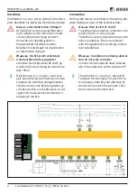
IT System beeing monitored
Tolerance of
U
n
.......................................... AC +10 % / DC +5%
Frequency range of
U
n
.........................................DC, 1…460 Hz
Measuring circuit
Measuring voltage Um (peak) .......................................... ±50 V
Internal resistance DC
R
i
..................................................≥ 70 kΩ
Internal resistance DC
R
i
[isoLR1685DP] .........................≥ 15 kΩ
Permissible extr. DC voltage
U
fg
[iso1685DP] ...........≤ DC 1600 V
Permissible extr. DC voltage
U
fg
[isoHV1685D] ........≤ DC 3150 V
Permissible extr. DC voltage
U
fg
[isoLR1685DP] .........≤ DC 720 V
Permissible system leakage capacitance
C
e
.................................
profile and device dependent ..................................0…2000 μF
Interfaces
Interface/protocol .............................. RS-485/BMS/Modbus RTU
Measuring circuit for ins. fault location [isoxx1685DP]
Locating current
I
L
DC ....................................................≤ 50 mA
Test cycle/Pause .................................................................2 s/4 s
Switching elements
Switching elements 3 changeover contacts:
K1 .......................................................(insulation fault Alarm 1)
K2 .......................................................(insulation fault Alarm 2)
K3 ...........................................................................(device error)
Contact data acc. to IEC 60947-5-1
Rated insulation voltage ....................................................250 V
Minimum contact rating .......................... 1 mA at AC/DC ≥ 10 V
Other
EMC .......................................................................IEC 61326-2-4
Degree of protection, built-in components (DIN EN 60529) IP30
Degree of protection, terminals (DIN EN 60529) ................. IP20
Überwachtes IT System
Toleranz von
U
n
..........................................AC +10 % / DC +5%
Frequenzbereich von
U
n
..................................... DC, 1…460 Hz
Messkreis
Messspannung Um (Spitzenwert) ......................................±50 V
Innenwiderstand DC
R
i
....................................................≥ 70 kΩ
Innenwiderstand DC
R
i
[isoLR1685DP] ............................≥ 15 kΩ
Zul. Fremdgleichspannung
U
fg
[iso1685DP] .............≤ DC 1600 V
Zul. Fremdgleichspannung
U
fg
[isoHV1685D] ..........≤ DC 3150 V
Zul. Fremdgleichspannung
U
fg
[isoLR1685DP] ...........≤ DC 720 V
Zulässige Netzableitkapazität
C
e
..................................................
profil- und geräteabhängig .....................................0…2000 μF
Schnittstellen
Schnittstelle/Protokoll ....................... RS-485/BMS/Modbus RTU
Messkreis für Isolationsfehlersuche [isoxx1685DP]
Prüfstrom
I
L
DC ..............................................................≤ 50 mA
Prüftakt/Pause ...................................................................2 s/4 s
Schaltglieder
Schaltglieder 3 Wechsler:
K1 .......................................................(Isolationsfehler, Alarm 1)
K2 .......................................................(Isolationsfehler, Alarm 2)
K3 ..........................................................................(Gerätefehler)
Kontaktdaten nach IEC 60947-5-1
Bemessungsisolationsspannung ........................................250 V
Minimale Kontaktbelastbarkeit .............. 1 mA bei AC/DC ≥10 V
Sonstiges
EMV .......................................................................IEC 61326-2-4
Schutzart Einbauten (DIN EN 60529) ....................................IP30
Schutzart Klemmen (DIN EN 60529) .....................................IP30
Alle Rechte vorbehalten.
Nachdruck und Vervielfältigung
nur mit Genehmigung des Herausgebers.
Bender GmbH & Co. KG
Postfach 1161 • 35301 Grünberg • Deutschland
Londorfer Str. 65 • 35305 Grünberg • Deutschland
Tel.: +49 6401 807-0 • Fax: +49 6401 807-259
E-Mail: [email protected] • www.bender.de
All rights reserved.
Reprinting and duplicating
only with permission of the publisher.
Bender GmbH & Co. KG
PO Box 1161 • 35301 Gruenberg • Germany
Londorfer Str. 65 • 35305 Gruenberg • Germany
Tel.: +49 6401 807-0 • Fax: +49 6401 807-259
E-Mail: [email protected] • www.bender.de
isoxx1685Dx-x25_D00272_02_Q_DEEN / 04.2019
/ pdf / © B
ender G
mbH & C
o. K
G, G
erman
y – S
ubjec
t t
o change!
The specified standar
ds tak
e in
to ac
coun
t the edition v
alid un
til
04/2019
unless other
wise indic
at
ed
.


