


I
C
aution
Disconnect from the IT system!
The insulation monitoring device must be
disconnected from the IT system before
insulation or voltage tests are carried out
at the installation. Otherwise the device
may be damaged
i
When the IT system to be monitored con-
tains galvanically coupled DC circuits,
take into consideration that: an insulati-
on fault can only be detected correctly
when the rectifier valves carry a mini-
mum correctly when the rectifier valves
carry a minimum current of > 10 A
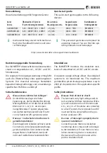
Mounting
Minimum distance to adjacent devices:
Lateral 0 mm, top 20 mm, bottom 20 mm!
Install the device by means of four M5 screws,
also refer to the drill holes shown in the dimen-
sion diagram. Align it in such a way that it is
vertically upright during operation and that the
system coupling (L1/+, L2/–) is on top.
I
V
orsiCht
Trennung vom IT-System!
Bei Isolations- und Spannungsprüfungen
an der Anlage muss das Isolationsüber-
wachungsgerät für die Dauer der Prüfung
vom IT-System getrennt sein. Andernfalls
kann das Gerät Schaden nehmen..
i
Wenn ein überwachtes IT-System galva-
nisch gekoppelte Gleichstromkreise ent-
hält, kann ein Isolationsfehler nur dann
richtig erfasst werden, wenn über die
Gleichrichterventile ein Mindeststrom von
> 10mA fließt.
Montage
Mindestabstand zu benachbarten Geräten:
Seitlich 0 mm, oben 20 mm, unten 20 mm!
Montieren Sie das Gerät mit 4 Schrauben M5,
siehe auch Bohrungen im Maßbild. Richten Sie
es so aus, dass es im Betrieb senkrecht steht und
die Netzankopplung (L1/+, L2/–) oben ist.
ISOMETER® isoxx1685Dx-x25
isoxx1685Dx-x25_D00272_02_Q_DEEN / 04.2019 3
ISOMETER
®
iso1685
PGH ON
246
125
40,5
40,75
51
368
383
401,5
106
64
8,75
5,2
61,8
76,6
39,8
55,7


