background image

10

ENG

IT

ES

2.1

STATUTORY REQUIREMENTS

GAS SAFETY (INSTALLATION AND USE)
REGULATIONS (as amended). It is the law
that all gas appliances are installed by a
registered person, in accordance with the
above regulations. Failure to install
appliances correctly could lead to
prosecution. It is in your own interest, and
that of safety, to ensure that the law is
complied with.
In addition to the above regulations, this
appliance must be installed in accordance
with the current IEE Wiring Regulations (BS
7671), Local Building Regulations, the
Building Standards (Scotland)
(Consolidation) Regulations, Byelaws of the
local water undertaking, and Health and
Safety Document No 635 “The Electricity at
Work Regulations 1989”. It should also be in
accordance with the relevant
recommendations in the current editions of
the following British Standards and Codes
of Practice: BS5449, BS5546, BS5440:1,
BS5440:2, BS6798, BS6891, and
BG.DM2, BS7074, and BS5482 for
propane installations.

Manufacturer’s instructions must NOT be
taken in any way as over-riding statutory
obligations.

2.2

BOILER POSITION

In siting the combination boiler, the following
limitations MUST be observed:
– The boiler is not suitable for external

installation. The position selected for
installation should be within the building,
unless otherwise protected by a suitable
enclosure, and MUST allow adequate
space for installation, servicing, and
operation of the appliance, and for air
circulation around it (section 2.4).

– This position MUST allow for a suitable

flue termination to be made. The
combination boiler must be installed on a
flat vertical wall which is capable of
supporting the weight of the appliance,
and any ancillary equipment.

– If the combination boiler is to be fitted in

a timber framed building it should be
fitted in accordance with the Institute of
Gas Engineers document for Gas
Installations In Timber Frame Housing,
Reference 16E/UP/7: 1998. If in doubt,
advice must be sought from the gas
supplier.

– If the appliance is installed in a room

containing a bath or shower, any
electrical switch or control utilising mains
electricity must be so situated that it
cannot be touched by a person using the
bath or shower. Attention is drawn to the
requirements of the current I.E.E. Wiring
Regulations (BS 7671), and in Scotland
the electrical provisions of the Building
Regulations applicable in Scotland.

– A compartment used to enclose the

appliance MUST be designed and
constructed specifically for this purpose.

An existing cupboard, or compartment,
may be used provided it is modified
accordingly.

– Where installation will be in an unusual

location, special procedures may be
necessary. BS6798 gives detailed
guidance on this aspect.

2.3

FLUE TERMINAL POSITION

Detailed recommendations for flue
installation are given in BS5440:1. The
following notes are for general guidance:
– The boiler MUST be installed so that the

terminal is exposed to the external air.

– It is important that the position of the

terminal allows free passage of air
across it at all times.

– It is ESSENTIAL TO ENSURE, in practice

that products of combustion discharging
from the terminal cannot re-enter the
building, or any other adjacent building,
through ventilators, windows, doors,
other sources of natural air infiltration, or
forced ventilation/air conditioning. If this
does occur, the appliance MUST be
turned OFF IMMEDIATELY and the gas

supplier consulted.

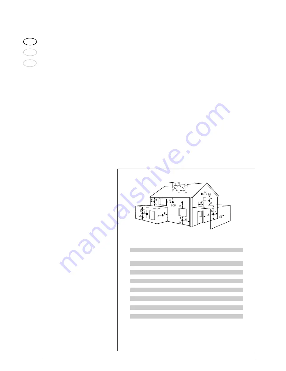
The minimum acceptable dimensions from
the terminal to obstructions and
ventilation openings are specified in fig. 4.

– If the terminal discharges into a pathway

or passageway check that combustion
products will not cause nuisance and that
the terminal will not obstruct the
passageway.

– Where the lowest part of the terminal is

fitted less than 2 m (78 in) above ground,
above a balcony or above a flat roof to
which people have access, the terminal
MUST be protected by a purpose
designed guard. 

– Where the terminal is fitted within 850

mm (34 in) of a plastic or painted gutter,
or 450 mm (18 in) of painted eaves, an
aluminium shield at least 1,500 mm (59
in) long must be fitted to the underside of
the painted surface.

– The air inlet/outlet flue duct MUST NOT

be closer than 25 mm (1 in) to
combustible material.

– In certain weather conditions the

terminal may emit a plume of steam. This
is normal but positions where this would
cause a nuisance should be avoided.

2

INSTALLATION

Fig. 4

TABLE 3
Terminal position

Minimum spacing in mm

A

Directly below an openable window,

300

air vent or any other ventilation opening

B

Below guttering, drain pipes or soil pipes

25 *

C/D

Below eaves, balconies or carport roof

25 *

E

From vertical drain pipes or soil pipes

75

F

From internal or external corners

25

G

Above adjacent ground, roof or balcony level

300

H

From a surface facing the terminal

600

I

From a terminal facing the terminal

1,200

J

From an opening in the carport (e.g. door, window into dwelling) 1,200

K

Vertically from a terminal on the same wall

1,500

L

Horizontally from a terminal on the same wall

300

M

Horizontally from a vertical terminal to a wall

300

N

Horizontally from an openable window or other opening

300

P

Above an openable window or other opening

300

Q

From an adjacent vertical terminal

600

* With “heat shield” installed in accordance to BS 5440 Pt1.

Summary of Contents for Metropolis DGT 25 BF

Page 1: ...lation and servicing instructions ENG IT ES ENSURE THAT THESE INSTRUCTIONS ARE LEFT FOR THE USER AFTER COMPLETION OF THE BENCHMARK SECTION Please read the Important Notice within this guide regarding...

Page 2: ...e recommended Avoid direct contact with sharp edges Avoid contact with any hot surfaces NOTICE Please be aware that due to the wet testing of the appliance there may some residual water in the hydraul...

Page 3: ......

Page 4: ...dards of installation and commissioning of domestic heating and hot water systems in the UK and to encourage regular servicing to optimi se safety efficiency and performance Benchmark is managed and p...

Page 5: ...the Benchmark Checklist in the use and maintenance section of this manual been completed IPX5D Important Information IT IS A STATUTORY REQUIREMENT THAT ALL GAS APPLIANCES ARE INSTALLED BY COMPETENT P...

Page 6: ...y water systems and is supplied fully assembled and equipped with complete valve packs The boiler can be used with a 24V room thermostat class II according to EN 60730 1 This booklet provides instruct...

Page 7: ...perature C 100 125 Smokes flow gr s 16 16 Losses after shutdown to 50 C W 73 Category II2H3 Type B22P 52P C12 32 42 52 82 Electrical supply 230V 50 hz fused at 3 A Internal fuse Line F1 6AT Weight kg...

Page 8: ...Combustion chamber 6 Gas valve 7 Water pressure valve 8 Circulator with air release vent 10 Hydrometer 11 Expansion vessel 12 D H W flow meter 13 By pass 14 D H W filter 15 Boiler discharge 16 3 BAR...

Page 9: ...s that set the burner output is reduced When this set temperature is reached the burner extinguishes and the fan stops The pump continues to run for 30 seconds to prevent residual heat build up in the...

Page 10: ...ided it is modified accordingly Where installation will be in an unusual location special procedures may be necessary BS6798 gives detailed guidance on this aspect 2 3 FLUE TERMINAL POSITION Detailed...

Page 11: ...W flow rate but does not exceed the maximum D H W pressure 1 3 point Where mains pressure exceed 6 bar a pressure reducing valve must be fitted in the D H W inlet 2 8 1 Treatment of water circulating...

Page 12: ...12 ENG IT ES TYPICAL SYSTEM DESIGN NOTE A drain cock should be installed at the lowest point of the heating circuit and beneath the appliance Fig 6 Fig 7 ALTERNATIVE METHODS OF FILLING A SEALED SYSTEM...

Page 13: ...rim flushing type the outlets are shrouded and it is impossible to attach a temporary hand held spray no anti syphonage device is necessary 2 11 FILLING THE WATER SYSTEM Open the C H flow and C H ret...

Page 14: ...duct is longer than 1 metre it is advisa ble to insulate the duct in order to avoid the formation of dew on the outside of the pipe when the weather is particularly cold With ducts with discharge posi...

Page 15: ...horizontal pipe 80 x 0 20 1 40 7 meter horizontal pipe 80 x 0 30 2 10 No 2 90 elbows 80 x 0 35 0 70 No 2 90 elbows 80 x 0 40 0 80 No 1 wall terminal 80 0 15 0 50 Total head loss 2 25 3 40 5 65 mm H2O...

Page 16: ...he boiler casing remove the two securing screws and tilt the control panel Connect the thermostat to the 6 pole ter minal board as indicated in the boiler elec trical diagram see diagram 2 19 after ha...

Page 17: ...SSO RED FLM VERDE GREEN ARANCIO ORANGE VCC GND OUT ROSSO RED ROSSO RED ROSSO RED 3 3 VDC 24 VDC 3 3 VDC 3 3 VDC 24 VDC 3 3 VDC 24 VDC 17 VDC 12 VDC 24 VDC R59 Fig 11 KEY F Fuse 1 6 AT TRA Ignition tra...

Page 18: ...T is only available if a resettable anomaly is signalled D H W SET Press the key to display the D H W temperature value set HEATING SET Press the key to display the heating temperature value set value...

Page 19: ...03 17 Pump heating activation delay 0 99 10 sec 1 01 18 Re ignition delay 0 10 Min 1 03 19 Modulation D H W flowmeter Disabled 01 1 Enabled 29 Anti legionella only D H W tank Disabled C 1 50 80 PARAME...

Page 20: ...nition failure with consequent activation of block can be due to Lack of gas The ignition electrode persists in dischar ging for max 10 seconds If the burner does not ignite the anomaly is signalled T...

Page 21: ...NTILATORE CAMERA STAGNA Fig 14 SEALED CHAMBER FAN PRESSURE SWITCH A B C RIFERIMENTO POSIZIONE BY PASS D Fig 15 KEY A By pass on B By pass off C Water pressure valve D Automatic air vent E Drain vent R...

Page 22: ...ws fig 18 Connect the column or a manometer to the intake down stream of the gas valve and disconnect the valve VENT pressure test point tube 5 fig 16 Remove the cap 1 from the modulator Connect the c...

Page 23: ...manifold unit Ideally use a vacuum clea ner and a soft brush so as to remove any dust particles that may have accumulated take care not to damage the insulation Clean the heat exchanger removing any...

Page 24: ...05 FLAME LOCKOUT ALARM 06 fig 20 a If the flame control has not detected the presence of the flame after a complete ignition sequence or for any other rea son the card cannot see the flame the boiler...

Page 25: ...general once a year should be adequate It is the law that a competent person such as a Gas Safe Register registered engineer must carry out any service work 4 7 1 Combustion Check Incorporated into t...

Page 26: ...ot affect the customer s statutory rights If yes and if required by the manufacturer has a water scale reducer been fitted CONDENSING BOILERS ONLY The condensate drain has been installed in accordance...

Page 27: ...er No Comments Signature Date Engineer Name Company Name Telephone No Gas Safe Register No Comments Signature Date Engineer Name Company Name Telephone No Gas Safe Register No Comments Signature Date...

Page 28: ...e the position of the sensing pipe and disconnect 6 REPLACEMENT OF PARTS If an electrical fault occurs on the appliance the preliminary electrical system checks must be carried out first When any serv...

Page 29: ...iler cover see 4 3 Close the flow and return isolation valves Drain the boiler using the fitted drain vent see fig 15 Disconnect the electrical connections to the pump Remove the four fixing screws Re...

Page 30: ...Water heat exchanger 014 6231362 NTC sensor 015 6318600 Sealed chamber front panel 016 6225636 Fan 017 6317900 Combustion chamber front panel 018 6318700 Combustion chamber side insulat 019 6264841 C...

Page 31: ...valve operation 062 6319630 Flowmeter 063 6147231 Straight fitting 1 2 15 064 6245000 Ball cock 3 4 x22 065 6245001 Ball cock 1 2 x15 066 6063601 Gas cock 1 2 068 2030227 Gasket 12x18x2 069 6226457 O...

Page 32: ...4258 Gas Water heat exchanger 014 6231362 NTC sensor 015 6318600 Sealed chamber front panel 016 6225636 Fan 017 6317900 Combustion chamber front panel 018 6318700 Combustion chamber side insulat 019 6...

Page 33: ...9630 Flowmeter 063 6147231 Straight fitting 1 2 15 064 6245000 Ball cock 3 4 x22 065 6245001 Ball cock 1 2 x15 066 6063601 Gas cock 1 2 068 2030227 Gasket 12x18x2 069 6226457 O ring 12bis diam 16x1 90...

Page 34: ...34 ENG IT ES NOTES...

Reviews: