


26
INSTALLATION
Locating the cooker
This appliance must be installed by an authorised person in accordance with this instruction
manual, local electrical regulations, local water regulations, local health regulations, Building
Code of Australia and any other government authority.
Side clearances - (Measurements B & C)
Where B, measured from the periphery of the
nearest burner to any vertical combustible surface,
or vertical combustible surface covered with
toughened glass or sheet metal, is less than
200mm, the surface shall be protected to a height
of C, of not less than 150mm above the hob for
the full dimension (width or depth) of the cooking
surface area.
Additional requirements for freestanding
and elevated gas cooking appliances -
(Measurements D & E)
Where D, the distance from the periphery of the
nearest burner to a horizontal combustible surface
is less than 200mm, then E shall be 10mm or
more, or the horizontal surface shall be above
the trivet.
Overheat clearances - (Measurement A)
The distance between the highest part of the hob of the cooking appliance should be higher
than 600mm for a range hood and higher than 750mm for an overhead exhaust fan.
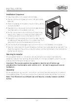
Installation of the anti-tilt plate
Determine position of cooker and anti-tilt plate.
Securely fix the anti-tilt plate to the floor with appropriate
fasteners.
Fasten the stability bolt bracket to the front frame with the
2 screws supplied.
Reposition the cooker back into the anti-tilt plate and then
mark the position of the stability bolt hole.
Pull the cooker back out and drill the bolt location hole.
Use a 10mm masonry or wood drill. When drilling into
concrete ensure a minimum hole depth of 30mm.
Reposition the cooker back into the anti-tilt plate, aligning
the stability bolt bracket with the 10mm drilled hole.
Then slide the bolt through the bracket and into the hole.
Connect electricity supply but do not turn on until
installation is completed.
Anti-tilt bracket