


V e l o c i t y K V M E x t e n d e r P r o d u c t M a n u a l , R e v . F , O c t . 2 0 2 1
Page 5
Note and Warning Symbols
Throughout this document you will notice certain symbols that bring your attention to important
information. These are
Notes
and
Warnings
. Examples are shown below.
Note: Important Notes appear in blue text preceded by a yellow exclamation point
symbol, as shown here.
A note is meant to call the reader’s attention to
helpful
information at a point in the text that is relevant to
the subject being discussed.
Warning!
All Warnings appear in red text, followed by blue text, and preceded by a red
stop sign, as shown here.
A warning is meant to call the reader’s attention to
critical
information at a point in the text that is
relevant to the subject being discussed.
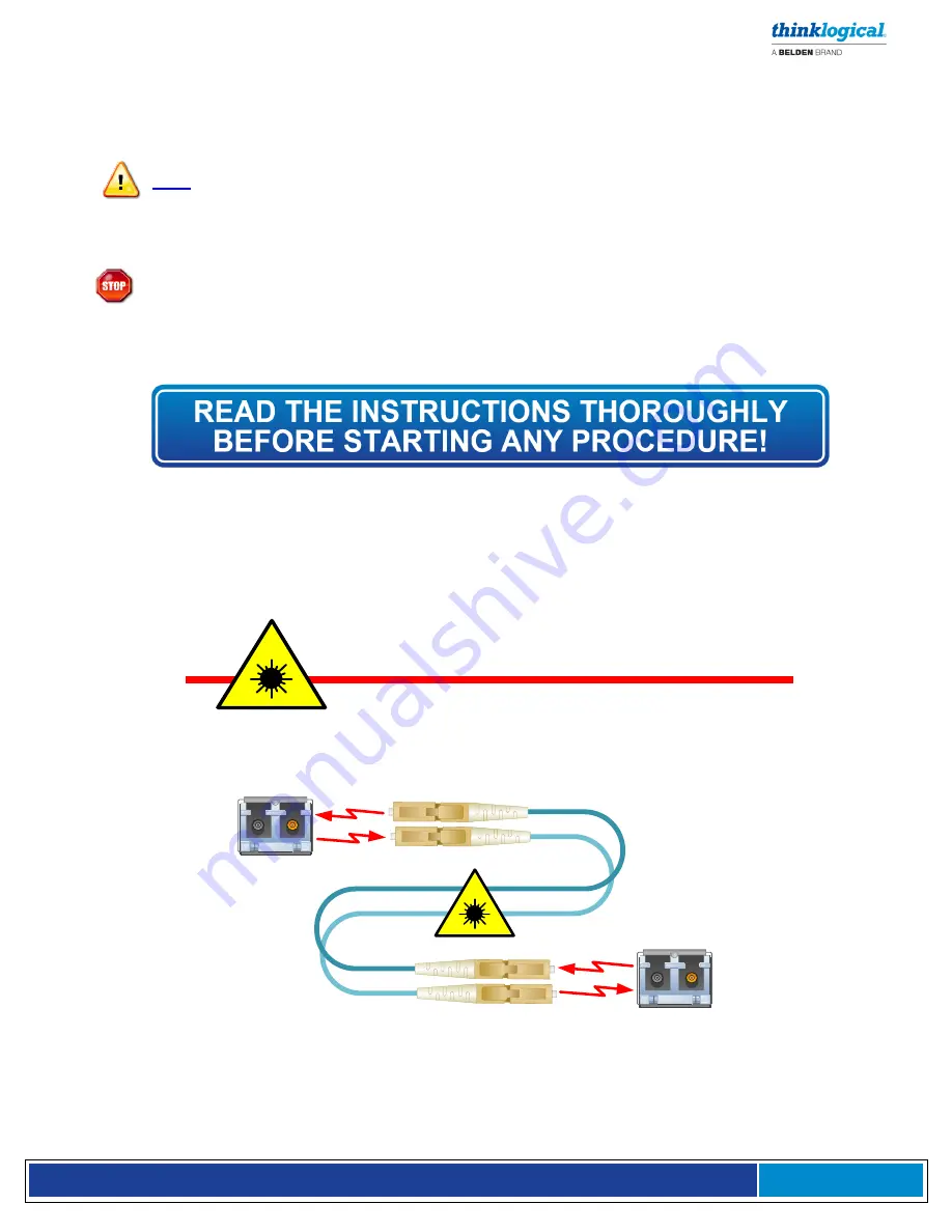
Class 1 Laser Information
TL
X Extenders and Matrix Switches, like all Thinklogical fiber-optic products, are designed and identified
as
Class 1 LASER products
This means the maximum permissible exposure (MPE) cannot be
exceeded when viewing the laser with the naked eye or with the aid of typical magnifying optics (e.g.
magnifying glass, eye loupe, etc.).
CLASS 1 LASERS do not require any special
precautions under conditions of normal use.
SFP
Modules
Fiber-Optic
Cables
Class 1 Lasers


