background image

8

Installation SPIDER II

Release 07 10/2013

Relevant for SPIDER II 8 TX/...FX... EEC and SPIDER II Giga 5T/2S 
EEC:

Note: 

LED or LASER components in compliance with IEC 60825-1 

(2007):
CLASS 1 LASER PRODUCT
CLASS 1 LED PRODUCT

National and international safety regulations

Make sure that the electrical installation meets local or nationally 
applicable safety regulations.

CE marking

The labeled devices comply with the regulations contained in the following 
European directive(s): 

2011/65/EU (RoHS)
Directive of the European Parliament and of the Council on the restriction 
of the use of certain hazardous substances in electrical and electronic 
equipment.

2004/108/EC (EMC)
Directive of the European Parliament and the council for standardizing the 
regulations of member states with regard to electromagnetic 
compatibility.

In accordance with the above-named EU directive(s), the EU conformity 
declaration will be at the disposal of the relevant authorities at the 
following address:

Hirschmann Automation and Control GmbH
Stuttgarter Str. 45-51
72654 Neckartenzlingen
Germany
Tel.: +49 1805 141538

The device can be used in the industrial sector.

Interference immunity: EN 61000-6-2

Emitted interference: EN 55022


Warning!

 This is a class A device. This device can cause interference in 

living areas, and in this case the operator may be required to take 
appropriate measures.

Note: 

The assembly guidelines provided in these instructions must be 

strictly adhered to in order to observe the EMC threshold values.

Summary of Contents for HIRSCHMANN SPIDER II

Page 1: ...et Rail Switch SPIDER II SPIDER II Giga SPIDER II PoE SPIDER II 8TX SPIDER II 8TX EEC SPIDER II 8TX 1FX EEC SPIDER II 8TX 1FX SM EEC SPIDER II 8TX 1FX ST EEC SPIDER II 8TX 2FX EEC SPIDER II 8TX 2FX SM EEC SPIDER II 8TX 2FX ST EEC SPIDER II Giga 5T 2S EEC SPIDER II Giga 5T EEC SPIDER II 8TX PoE SP SP SP SP SP SP SP SP SP SP P 1 2 3 4 5 6 7 8 ...

Page 2: ...tures described here are binding only if they have been expressly agreed when the contract was made This document was produced by Hirschmann Automation and Control GmbH according to the best of the company s knowledge Hirschmann reserves the right to change the contents of this document without prior notice Hirschmann can give no guarantee in respect of the correctness or accuracy of the informati...

Page 3: ...1 4 Display elements 17 1 4 1 Device state 17 1 4 2 Port state 17 2 Installation 18 2 1 Unpacking the package and checking the content 19 2 2 Installing an SFP transceiver optional 19 2 3 Connecting the terminal block for the supply voltage and the grounding 20 2 4 Mounting the device on the DIN rail 20 2 5 Installing the terminal block start up procedure 21 2 6 Connecting network cables 22 2 6 1 ...

Page 4: ...R II Release 07 10 2013 4 Disassembly 23 4 1 Removing the device from the DIN rail 23 4 1 1 SPIDER II without PoE 23 4 1 2 SPIDER II 8TX PoE 24 4 2 Removing the SFP transceivers 24 5 Technical data 25 A Further Support 35 ...

Page 5: ...ltage in compliance with IEC EN 60950 1 Connect the ground connector before you set up the other connections When removing the connections you remove the ground connector last Relevant for North America To be used in class 2 circuits The device may only be connected to a supply voltage of class 2 that fulfills the requirements of the National Electrical Code Table 11 b Relevant for North America F...

Page 6: ...led in a living area or office environment the device must be operated exclusively in switch cabinets with fire protection characteristics in accordance with EN 60950 1 CAUTION ELECTRIC SHOCK Solely connect a supply voltage that corresponds to the type plate of your device Never insert sharp objects small screwdrivers wires etc into the inside of the device Failure to follow these instructions can...

Page 7: ...rcuits and devices or systems in accordance with current safety engineering standards trained or directed in the care and use of appropriate safety equipment in accordance with the current standards of safety engineering trained in providing first aid General safety instructions This device is operated by electricity You must follow precisely the prescribed safety requirements for the voltage conn...

Page 8: ...t 2004 108 EC EMC Directive of the European Parliament and the council for standardizing the regulations of member states with regard to electromagnetic compatibility In accordance with the above named EU directive s the EU conformity declaration will be at the disposal of the relevant authorities at the following address Hirschmann Automation and Control GmbH Stuttgarter Str 45 51 72654 Neckarten...

Page 9: ...ce must accept any interference received including interference that may cause undesired operation Appropriate testing has established that this device fulfills the requirements of a class A digital device in line with part 15 of the FCC regulations These requirements are designed to provide sufficient protection against interference when the device is being used in a business environment The devi...

Page 10: ...l document contains a device description safety instructions a display description and other information that you require to install the device before starting with the configuration of the device Legend The symbols used in this manual have the following meanings Listing Work step Subheading ...

Page 11: ... devices work without a fan You have the option of choosing various media to connect terminal devices and other network components twisted pair cable multimode F O singlemode F O The Hirschmann network components help you ensure continuous communication across all levels of the company 1 2 Description of the device variants The devices differ with regard to the number of interfaces and the media t...

Page 12: ...000 Mbit s twisted pair port SFP slot for 1000 Mbit s F O port SPIDER II 8TX 8 SPIDER II 8TX EEC 8 SPIDER II 8TX 1FX EEC 8 1 SPIDER II 8TX 1FX SM EEC 8 1 SPIDER II 8TX 2FX EEC 8 2 SPIDER II 8TX 2FX SM EEC 8 2 SPIDER II 8TX 1FX ST EEC 8 1 SPIDER II 8TX 2FX ST EEC 8 2 SPIDER II Giga 5T EEC 5 SPIDER II Giga 5T 2S EEC 5 2 SPIDER II Giga 5T EEC PRO 5 SPIDER II Giga 5T 2S EEC PRO 5 2 SPIDER II Giga 5T E...

Page 13: ...s 9 to 10 SPIDER II 8TX 2FX EEC DSC multimode socket for 100 Mbit s F O port SPIDER II 8TX 2FX SM EEC DSC singlemode socket for 100 Mbit s F O port 6 Port 9 ST multimode socket for 100 Mbit s F O port 7 Ports 9 to 10 ST multimode socket for 100 Mbit s F O port Table 2 Overview of the device variants without gigabit ports SPIDER II 8TX SPIDER II 8TX SPIDER II 8TX EEC SPIDER II 8TX 1FX EEC SPIDER II...

Page 14: ... F O port 2 Ports 1 to 5 RJ45 socket for 10 100 1000 Mbit s twisted pair port 3 LED display element 4 3 pin terminal block for supply voltage Table 3 Overview of the device variants with gigabit ports SPIDER II Giga Port priority Traffic classes IEEE 802 1D traffic type 0 1 Best Effort default 1 0 Background 2 0 Standard 3 1 Excellent Effort business critical 4 2 Controlled load streaming multimed...

Page 15: ...EE 802 3af performance classes up to a maximum output power of 15 4 W The 4 PoE capable ports are the 4 bottom ports of the device see figure 3 on page 21 The PoE ports are indicated in red on the device The voltage is supplied through the wire pairs transmitting the signal phantom voltage The individual ports are not electrically insulated from each other The following conditions are met in accor...

Page 16: ...he front panel This port is an RJ45 socket The 10 100 Mbit s PoE port allows you to connect network components as a PoE voltage sink according to the standard IEEE 802 3 10BASE T 100BASE TX and IEEE 802 3af This port supports Autonegotiation Autopolarity Autocrossing 100 Mbit s half duplex mode 100 Mbit s full duplex mode 10 Mbit s half duplex mode 10 Mbit s full duplex mode Power over Ethernet Po...

Page 17: ... and 8TX 2FX SM EEC these ports are DSC connectors For the device variants 8TX 1FX ST EEC and 8TX 2FX ST EEC these ports are ST connectors The 100 Mbit s F O port offers you the ability to connect network components according to the IEEE 802 3 100BASE FX standard This port supports Full duplex mode Pin Function PoE voltage 1 RD Receive path Minus terminal 2 RD Receive path Minus terminal 3 TD Tran...

Page 18: ...tiation Full duplex mode Note Verify that you connect solely optical ports with the same optical transmission properties with each other 1 4 Display elements 1 4 1 Device state These LEDs provide information about conditions which affect the operation of the whole device Figure 1 Device status LEDs 1 Power LED P 1 4 2 Port state Along with the LED for the device status there is an LED for the port...

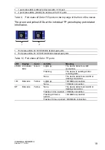
Page 19: ... 10 100 1000 Mbit s twisted pair ports Table 10 Port status LEDs for TP ports LED Display Color Activity Meaning LS DA Link status data Green Lights up The device detects a valid connection Flashing The device is sending and or receiving data None The device detects an invalid or missing connection 100 Data rate Yellow Lights up 100 Mbit s connection None 10 Mbit s connection SP Data rate Yellow N...

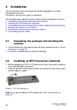
Page 20: ...ng the device on the DIN rail Installing the terminal block start up procedure Connecting network cables 2 1 Unpacking the package and checking the content Check whether the package includes all items named in section Scope of delivery on page 29 Check the individual parts for transport damage 2 2 Installing an SFP transceiver optional Before attaching an SFP or XFP transceiver first remove the pr...

Page 21: ...vice Connect the ground connection Connect the supply voltage lines 2 4 Mounting the device on the DIN rail CAUTION ELECTRIC SHOCK Solely connect a supply voltage that corresponds to the type plate of your device Failure to follow these instructions can result in injury or equipment damage Figure Pin Assignment Voltage range DC 1 24 V 9 6 V 32 V SPIDER II 8TX PoE 18 V 32 V 2 0 V 3 Ground connectio...

Page 22: ...nted 35 mm DIN rail according to DIN EN 60715 proceed as follows Slide the upper snap in guide of the device into the DIN rail Press the media module downwards onto the clip in bar Snap in the device Figure 3 Mounting on the DIN rail 2 5 Installing the terminal block start up procedure CAUTION ELECTRIC SHOCK Solely connect a supply voltage that corresponds to the type plate of your device Failure ...

Page 23: ...r 10 100 Mbit s twisted pair port on page 15 Install the data lines according to your requirements 2 6 2 10 100 Mbit s PoE port You will find further information under 10 100 Mbit s PoE port on page 15 Install the data lines according to your requirements 2 6 3 10 100 1000 Mbit s twisted pair port You will find further information under 10 100 1000 Mbit s twisted pair port on page 16 Install the d...

Page 24: ...he product when it is operated normally Operate this device according to the specifications see on page 25 Technical data Depending on the degree of pollution in the operating environment check at regular intervals that the ventilation slots in the device are not obstructed Note You will find information about the complaints and returns procedures in the Internet under http www beldensolutions com...

Page 25: ...m the DIN rail you proceed as follows Insert a screwdriver horizontally below the housing into the locking gate Pull the locking gate down without tilting the screwdriver Fold the device up Figure 4 Removal from the DIN rail 4 1 2 SPIDER II 8TX PoE To remove the device from the DIN rail press the device downwards and pull it out from under the DIN rail ...

Page 26: ...I Release 07 10 2013 Figure 5 Removal from the DIN rail 4 2 Removing the SFP transceivers Pull the module out of the socket by means of the opened lock Close the module with the protective cap Figure 6 F O SFP transceiver 1 2 ...

Page 27: ... without PoE 9 6 to 32 0 V DC Safety extra low voltage SELV Relevant for North America NEC Class 2 power source max 5A Operating voltage SPIDER II 8TX PoE 18 0 to 32 0 V DC Buffer time min 10 ms at 20 4 V DC Potential difference between incoming voltage and housing Potential difference from incoming voltage 24 V DC 32 V DC Potential difference from incoming voltage ground 32 V DC Environment Stora...

Page 28: ... IEC EN 61000 4 2 Electrostatic discharge Contact discharge Air discharge SPIDER II 8TX SPIDER II Giga 4 kV 6 kV 8 kV IEC EN 61000 4 3 Electromagnetic field 80 MHz 2700 MHz 20 V m IEC EN 61000 4 4 Fast transients burst DC power line Data line 2 kV 4 kV IEC EN 61000 4 5 Voltage surges DC power line line line DC Power Line line ground Data line line ground SPIDER II without PoE SPIDER II 8TX PoE 1 k...

Page 29: ...DER II 8TX F O type Wave length Fiber System attenuatio n Example for F O line length Fiber attenuati on BLP dispersion FX EEC FX ST EEC MM 1300 nm 50 125 µm 0 8 dB 0 5 km 1 0dB km 800 MHz km FX EEC FX ST EEC MM 1300 nm 62 5 125 µm 0 11 dB 0 4 km 1 0 dB km 500 MHz km FX SM EEC SM 1300 nm 9 125 µm 0 16 dB 0 30 km 0 4 dB km 3 5 ps nm km Table 13 F O port 100BASE FX Product code M SFP Wave length Fib...

Page 30: ...ved Product code M SFP BIDI Wave length TX Wave length RX Fiber System attenuat ion Example for F O line length a a including 3 dB system reserve when compliance with the fiber data is observed Fiber attenuati on Dispersion Type A LX LC EEC SM 1310 nm 1550 nm 9 125 µm 0 11 dB 0 20 km 0 4 dB km 3 5 ps nm km Type B LX LC EEC SM 1550 nm 1310 nm 9 125 µm 0 11 dB 0 20 km 0 25 dB km 19 ps nm km Type A L...

Page 31: ...001 Rail Switch SPIDER II 8 TX 1FX EEC 943 958 111 Rail Switch SPIDER II 8 TX 2FX EEC 943 958 211 Rail Switch SPIDER II 8 TX 1FX SM EEC 943 958 131 Rail Switch SPIDER II 8 TX 2FX SM EEC 943 958 231 Rail Switch SPIDER II 8 TX 1FX ST EEC 943 958 121 Rail Switch SPIDER II 8 TX 2FX ST EEC 943 958 221 Rail Switch SPIDER II Giga 5T EEC 943 962 002 Rail Switch SPIDER II Giga 5T 2S EEC 943 963 002 Rail Sw...

Page 32: ...C 943 975 001 M SFP BIDI Type B LH LC EEC 943 975 002 M SFP BIDI Bundle LX LC EEC type A B 943 974 101 M SFP BIDI Bundle LH LC EEC type A B 943 975 101 Other accessories Order number Rail Power Supply RPS 30 943 662 003 Rail Power Supply RPS 80 EEC 943 662 080 Rail Power Supply RPS 120 EEC CC 943 662 121 Name UL 508 Safety for Industrial Control Equipment EN 55022 Information technology equipment ...

Page 33: ...Installation SPIDER II Release 07 10 2013 33 ...

Page 34: ...34 Installation SPIDER II Release 07 10 2013 ...

Page 35: ...0 E mail inet ap belden com Hirschmann Competence Center The Hirschmann Competence Center is ahead of its competitors Consulting incorporates comprehensive technical advice from system evaluation through network planning to project planning Training offers you an introduction to the basics product briefing and user training with certification The current technology and product training courses can...

Page 36: ......
Reviews: