background image

20

XCU Universe XF XF Transmission Base Station User’s Guide (v1.4)

Chapter 2  - Installation

2.5.2  Dry contact with multiple XCUs

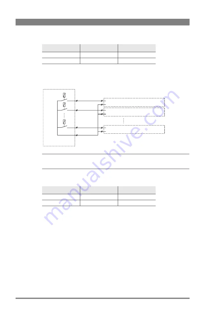
This is an example of an On Air signalling with multiple XCUs using a common contact.

Note


Note


Use either Send or Return only, but do not mix.

If a contact is closed, the corresponding function is Active or Inactive, depending on the 
selection in the 

INSTALL   >   SIGNALLING   INPUT

 menu:

Menu setting  

Input is shorted:

Input is open:

LH (low-high)

Function is Active

Function is Inactive

HL (high-low)

Function is Inactive

Function is Active

On-Air (Tally) 1

On-Air (Tally) 2

On-Air (Tally) n

Common

External On-Air signalling
(common contact)

On-Air in ext. send (pin 4)

Signalling connector

On-Air in ext. return (pin 12)

Base Station 1

Signalling connector

Base Station 2

Signalling connector

Base Station n

On-Air in ext. send (pin 4)
On-Air in ext. return (pin 12)

On-Air in ext. send (pin 4)
On-Air in ext. return (pin 12)

Menu setting  

Input is shorted:

Input is open:

LH (low-high)

Function is Active

Function is Inactive

HL (high-low)

Function is Inactive

Function is Active

Summary of Contents for Grass Valley XCU Universe XF

Page 1: ...Communication Transmission Camera Power Cable Power On Air XCU UNIVERSE UXF XF FIBER 42 3922 496 32391 October 2018 v1 4 XCU Universe XF User s Guide XF Transmission Base Station...

Page 2: ...interference when operated in a commercial environment Operation of this product in a residential area is likely to cause interference in which case the user at his own expense will be required to tak...

Page 3: ...p the control network 18 2 4 Setting up intercom 18 2 5 Setting up studio signalling 19 2 5 1 Dry contact 19 2 5 2 Dry contact with multiple XCUs 20 2 5 3 Common ground 21 2 5 4 Voltage level 22 2 5 5...

Page 4: ...ber connector 51 6 1 3 Main video for HD 1080i 720p video modes 52 6 1 4 Main video for 3G 1080p video modes 53 6 1 5 Main video for 4K video modes 54 6 1 6 Main video for HS and XS video modes 55 6 1...

Page 5: ...try to use the containers and materials of the original packaging Attach a tag indicating the type of service required return address model number full serial number and the return number which will b...

Page 6: ...erruption of 5 s EN55103 2 EMC Immunity following the provisions of the EMC Directive 2004 108 EC the Low Voltage Directive 2006 95 EC FCC Class A Statement This product generates uses and can radiate...

Page 7: ...ity to operate this equipment Cautions and Warnings Read and comply with the warning and caution notices that appear in the manual Warnings indicate danger that requires correct procedures or practice...

Page 8: ...in may result in hazardous radiation exposure To ensure proper use of this product please read this instruction manual carefully and retain for future reference Should the unit ever require maintenanc...

Page 9: ...nt sleeves and the interior and exterior of connector shells For plugs the interior surfaces of alignment sleeves and the tips of ferrules are to be cleaned with a cleaning stick treated with the appr...

Page 10: ...identifying the terminals in your plug proceed as follows The wire colored GREEN AND YELLOW must be connected to the terminal on the plug marked with the letter E or by the safety earth symbol or colo...

Page 11: ...w to install and operate the XCU Universe XF It provides the information necessary to install set up and operate the unit in different configurations 1 1 2 Related documents Before proceeding check th...

Page 12: ...to quickly and easily transfer XCU Universe XFs between OB vans studios or anyplace The cradle concept allows for moving boxes easily and quickly between locations such as trucks and studios Pre mount...

Page 13: ...of 3 000 m 10 000 ft and beyond using hybrid fiber cables 1 2 3 Camera control and monitoring You can access the XCU menu which contains all operational settings from an Operational Control Panel In...

Page 14: ...80p179 82 3X with LDX 86 HS and LDX 86 XS Cameras Transports the following digital signals from camera to XCU main video signal four audio channels including embedded digital audio two intercom channe...

Page 15: ...r installation instructions Make sure that both front and back end of the rails are attached to the rack Allow a minimum distance of 30 cm 11 8 in between the secured points There should be a blind un...

Page 16: ...recautions Use proper shock absorbers for the rack to prevent damage during transport To prevent any horizontal movement of the cradle and XCU during transport make sure there is as little horizontal...

Page 17: ...g and other studio infrastructure can be found further down this chapter 2 2 Mounting the XCU To mount the XCU into the cradle proceed as follows Place the XCU onto the sliding rails of the cradle sli...

Page 18: ...fault the Ethernet connection is set up for Auto IP configuration 2 4 Setting up intercom Connect the studio intercom system to the rear of the XCU Universe XF Both a two and four wire cabling can be...

Page 19: ...d Return 2 5 1 Dry contact Note Note A common return not ground can be used for all three functions ISO On Air and Call If a contact is closed the corresponding function is Active or Inactive dependin...

Page 20: ...ed Input is open LH low high Function is Active Function is Inactive HL high low Function is Inactive Function is Active On Air Tally 1 On Air Tally 2 On Air Tally n Common External On Air signalling...

Page 21: ...Air in ext return pin 12 Base Station 1 Signalling connector Base Station 2 Signalling connector Base Station n On Air in ext pin 4 On Air in ext return pin 12 On Air in ext pin 4 On Air in ext retur...

Page 22: ...function state depends on the selection in the INSTALL SIGNALLING INPUT menu Menu setting Input is 0 to 2 5V Input is 4 to 24V LH low high Function is Active Function is Inactive HL high low Function...

Page 23: ...Inactive or Active The function state depends on the selection in the INSTALL SIGNALLING INPUT menu Menu setting Input is open Input is 4 to 24V OH open high Function is Active Function is Inactive H...

Page 24: ...ine level is 32 dBu 2 7 Using private data Private data channels can be used for sending serial data via the transmission cable For example electronic scriptboard or character data for a video display...

Page 25: ...ss and navigate the internal XCU menu 3 2 Setting the camera number Push and hold the Forward button 5 for two seconds until the following selection menu appears Select the Change camera number option...

Page 26: ...l the following selection menu appears Select the XCU Menu control option and push the Forward button to select Or push the Back button to return to the main display status The navigation pad appears...

Page 27: ...e XCU Universe XF or the OCP 400 to access the XCU menu The functions of the XCU are grouped into menus and sub menus When accessed the main menu appears on the monitor outputs The main menu screen sh...

Page 28: ...menu Press the Select button to leave the menu This is the recommended way of leaving the system menu The menu system disappears after a few seconds when you stop navigating This delay can be set in...

Page 29: ...o change the analog value Press the Select button to return the cursor to the function list Using Recall File to undo changes If you make changes to the settings in the menu and you decide not to keep...

Page 30: ...nus 3 5 1 Studio interface setup A four wire or a two wire studio system can be connected to the XCU In the AUDIO INTERCOM INTERCOM menu select the Wire Mode for the engineering ENG production PROD an...

Page 31: ...pes are available Split default and Full 3 7 Timing All main HD Video SD and monitoring output signals coming from the XCU are in phase Still due to different cable lengths or other delays the signals...

Page 32: ...32 XCU Universe XF XF Transmission Base Station User s Guide v1 4 Chapter 3 Configuration...

Page 33: ...e display shows the number of the camera connected to the XCU It can also show configuration and diagnostic information Use the up and down arrows next to the display to loop through three different s...

Page 34: ...icates a power supply error e g a power overload Cable indicator This green indicator lights when a transmission cable is correctly connected between the camera and XCU A blinking red light indicates...

Page 35: ...teps to replace the fuses located in the mains entry Indication Description Cable or signal quality is OK Cable or signal quality is below optimum transmission is still in operation The quality level...

Page 36: ...older to unclip both side of the fuseholder 2 Extract the fuseholder from the mains entry by pulling of the small clip at the bottom of the fuseholder 3 Replace both fuses 4 Insert the fuseholder unti...

Page 37: ...signal Noise Slicer 0 99 10 User 1 Sets the level of the Noise Slicer Coarse Fine 0 99 90 User 1 Sets SD Detail balance between coarse and fine structures 0 coarse 99 fine Level Dependence 0 99 30 Us...

Page 38: ...l signal Noise Slicer 0 99 10 User 1 Sets the level of the Noise Slicer Coarse Fine 0 99 90 User 1 Sets HD Detail balance between coarse and fine structures 0 coarse 99 fine Level Dependence 0 99 30 U...

Page 39: ...olt Cur drive 4wire 2wire 4wire Service Advanced settings 2 4 wire 4wire 2wire 4wire Service Advanced settings Level 0dB 6dB 6dB User 1 Selects intercom channel attenuation only available in 4wire mod...

Page 40: ...000 0 User 0 Sets timing delay for IP Media Network output stream in s Shift Pixels 0 1920 0 Service Advanced settings Lines 0 1080 0 Service Advanced settings Time Date Time time User 2 Shows current...

Page 41: ...er 0 BS IP digit 4 1 254 0 User 0 CAM IP digit 1 1 250 0 User 0 Selects camera head IP address in the C2IP control network when IP mode is set to manual CAM IP digit 2 0 255 0 User 0 CAM IP digit 3 0...

Page 42: ...BNC IP IP Service Advanced settings Pref TP Src BNC IP IP User 3 Selects source signal for Teleprompter video input BNC signal from BNC connector rear of XCU IP signal from IP Media Network Used Src B...

Page 43: ...d for 3G outputs when XCU runs in 3G video mode Level A direct mapping Level B dual link mapping 2SI Payload ID 2SI 2SI 3G User 3 Selects Payload ID for 4K video modes 2SI 2 sample interleave 3G Quad...

Page 44: ...ink type Unknown 10Mb Half 10Mb Full 100Mb Half 100Mb Full Negotiate Unknown User 2 Advanced settings Loopback test Loopback test Off On Off Service Advanced settings Data count Service Advanced setti...

Page 45: ...Overload Short Cam Off Cam On Error Error User 0 Advanced settings Int Error Unknown VMtest STtest CStest FBtest Start Shutdown nonFlex Family Unknown User 0 Advanced settings Package Ok Not Ok Not O...

Page 46: ...nced settings Data Error Stats UART Errors 0 65335 0 Service Advanced settings Decompr Errors 0 65335 0 Service Advanced settings IP Errors 0 65335 0 Service Advanced settings TCP Errors 0 65335 0 Ser...

Page 47: ...0p50 1080p59 1080p50 1080i47 Unknown User 1 Advanced settings Teleprompter Unknown None PAL NTSC Unknown User 0 Advanced settings Reference In Unknown 1080i59 1080i50 720p59 720p50 1080p59 1080p50 108...

Page 48: ...2 Advanced settings Maximum Temp User 2 Advanced settings Menu item Settings Default Level Description Menu item Settings Default Level Description Info Files Storage None SDcard USB SD USB None Servi...

Page 49: ...49 Chapter 5 XCU menu reference Format Off Running Off Service Advanced settings Lic Partition Status Unknown Busy OK Error NonGV Init Unknown Service Advanced settings USB available No Yes No Service...

Page 50: ...50 XCU Universe XF XF Transmission Base Station User s Guide v1 4 Chapter 5 XCU menu reference...

Page 51: ...Monitoring HD Video out A B C Live Effect D SDI Out Ext 2 in Ext 3 in Ext 1 out Ext 1 in HD SDI SDI CVBS Ref out TP out 2 1 3 Pin Description 1 Neutral 2 Line 3 Earth Mains input voltage 100 to 240 VA...

Page 52: ...s switchable Connector Signal Monitoring HD SDI BNC 0 8 Vpp 75 HD SDI 1 5 Gb s 1080i or 720p output signal with menu text and indicators inserted Monitoring SDI BNC 0 8 Vpp 75 digital SDI output sign...

Page 53: ...292M 1 5 Gbit s with embedded audio in 1080i or 720p modes or SMPTE 259M 270 Mbit s Connector Signal Monitoring HD SDI BNC 0 8 Vpp 75 HD SDI 1 5 Gb s 1080i or 720p output signal with menu text and in...

Page 54: ...2SI Link 1 HD Video out B 2x 2x BNC 0 8 Vpp 75 3G SDI 3 Gb s Quad Link 2 top right frame or 2SI Link 2 HD Video out C 2x 2x BNC 0 8 Vpp 75 3G SDI 3 Gb s Quad Link 3 bottom left frame or 2SI Link 3 Liv...

Page 55: ...with embedded audio HD Video out C 2x 2x BNC 75 HD SDI 3 Gb s phase 3 in HS modes or phase 5 6 in XS modes with embedded audio Live Effect D 2x 2x BNC 75 HD SDI 1 5 or 3 Gb s with embedded audio Conne...

Page 56: ...is output signal is always looped through even when the XCU is not mounted in its cradle Connector Signal Ext 1 in External 1 HD SDI or SDI video input Ext 2 in External 2 HD SDI or SDI video input Ex...

Page 57: ...through output signal Pin Description 1 Preview output ext relay contact 10 2 Call output ext relay contact 10 3 ISO input ext dry contact 4 On Air input ext dry contact 5 Call input ext dry contact...

Page 58: ...ut 2 wire in out 10 Prod in return 4 wire only 11 Eng in shield 4 wire only 12 Eng in return 4 wire only 13 Eng out return 4 wire out 2 wire in out 14 Prog in return 4 wire only 15 Housing Pin Descrip...

Page 59: ...t connector BNC connector 2 channel AES EBU compliant audio output 1 0 Vpp 75 BNC connector This connector carries the digitally converted audio channel 1 and 2 from the camera s Mic 1 and Mic 2 conne...

Page 60: ...er 6 Connectors and signals 6 1 17 Analog Audio OUT 2 connector Pin Description 1 Audio shield 2 Audio output 3 Audio return XLR 3 pin male connector Sensitivity range 64 dBu to 22 dBu Signal at pin 2...

Page 61: ...itude max 15 420 m 50 000 ft Power Power requirements 100 to 240 VAC 50 to 60 Hz Power consumption 450 W max fully equipped Power connection IEC type 3 pin male Transmission Transmission connector s L...

Page 62: ...ate data in out 115 kbits s TTL levels RS 232 Analog audio outputs Analog audio outputs 2x XLR 3 0 6 dBu 1 5 dB max 18 dBu 600 max gain 70 dB Frequency response 40 Hz to 15 kHz 1 3 dB 1 kHz 10 dBu out...

Page 63: ...U Universe XF XF Transmission Base Station User s Guide v1 4 63 Chapter 7 Specifications 7 2 Dimensions Communication Transmission Camera Power Cable Power On Air XF Fiber 42 438 mm 440 mm 88 mm 482 m...

Page 64: ...64 XCU Universe XF XF Transmission Base Station User s Guide v1 4 Chapter 7 Specifications...

Page 65: ...XCU Universe XF XF Transmission Base Station User s Guide v1 4 65...

Page 66: ...Copyright Grass Valley Nederland B V...

Reviews: