18
XCU Universe XF XF Transmission Base Station User’s Guide (v1.4)
Chapter 2 - Installation
2.3 Setting up the control network
The XCU is connected to the control network hub or router via an Ethernet cable (straight-
through, not cross-over) via the C2IP (RJ45) connector. An OCP 400 (Operational Control Panel)
and, if required an MCP 450 (Master Control PC), are also connected to the Ethernet network
via a hub or router. An OCP 400 can also be connected directly to the XCU using a (cross-over
or a straight-through) Ethernet cable.
The IP address and other options for the Ethernet connection can be set up in the XCU menu.
☞
Note
☞
Note
By default, the Ethernet connection is set up for Auto IP configuration.
2.4 Setting up intercom
Connect the studio intercom system to the rear of the XCU Universe XF. Both a two and four-
wire cabling can be used. In the
AUDIO/INTERCOM > INTERCOM > ENG > WIRE MODE
menu
select the cabling system: 2wire or 4wire.
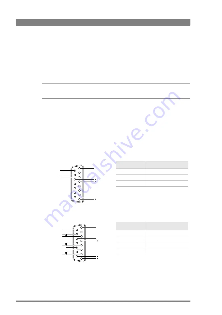
The wiring of the panel connector is shown below for two-wire and four-wire systems.
Two-wire systems
Four-wire systems
Signal
Value
Signal level
0 dBu (RMS)
Load impedance
200
Voltage level
max. 40 VDC
8
1
15
9
Housing
Prod
Housing
Eng in/out
Prod in/out
Signal
Value
Output signal level
+6 or 0 dBu (RMS) selectable
Output impedance
max. 50
symmetrical
Input signal level
+6 or 0 dBu (RMS) selectable
Impedance
min. 9 k
symmetrical
8
1
15
9
Housing
Eng in/out
Prod in/out
Housing
Prog in ret
Prog in
Prod in ret
Prod in
Eng in ret
Eng in
Summary of Contents for Grass Valley XCU Universe XF
Page 32: ...32 XCU Universe XF XF Transmission Base Station User s Guide v1 4 Chapter 3 Configuration...
Page 50: ...50 XCU Universe XF XF Transmission Base Station User s Guide v1 4 Chapter 5 XCU menu reference...
Page 64: ...64 XCU Universe XF XF Transmission Base Station User s Guide v1 4 Chapter 7 Specifications...
Page 65: ...XCU Universe XF XF Transmission Base Station User s Guide v1 4 65...


