background image

10

Cabling and Connections

Mainframe Layout and Connections

Mainframe Layout and Connections

Mainframe Overview

The Kula AV mainframe has 1 card that has all the Mix Effects and Input/Output video 
processing.

Kula AV Mainframe Front Card Location

Main Card

Summary of Contents for grass valley KULA AV

Page 1: ...Installation Manual 13 06512 020 2020 07 13 KULA AV PRODUCTION SWITCHER ...

Page 2: ...carefully By using Kula AV documentation you agree to the following terms and conditions Grass Valley hereby grants permission and license to owners of Kula AV to use their product manuals for their own internal business use Manuals for Grass Valley products may not be reproduced or transmitted in any form or by any means electronic or mechanical including photocopying and recording for any purpos...

Page 3: ... to making any other equipment connections Identifies an external protective grounding terminal which may be connected to earth ground as a supplement to an internal grounding terminal Indicates that static sensitive components are present which may be damaged by electrostatic discharge Use anti static procedures equipment and surfaces during servicing Indicates that the equipment has more than on...

Page 4: ...t use liquid or aerosol cleaners use only a damp cloth Dangerous voltages may exist at several points in this equipment To avoid injury do not touch exposed connections and components while power is on High leakage current may be present Earth connection of product is essential before connecting power Prior to servicing remove jewelry such as rings watches and other metallic objects To avoid fire ...

Page 5: ...personnel This unit may have more than one power supply cord Disconnect all power supply cords before servicing to avoid electric shock Follow static precautions at all times when handling this equipment Servicing should be done in a static free environment To reduce the risk of electric shock plug each power supply cord into separate branch circuits employing separate service grounds Electrostati...

Page 6: ...rité et avis importants La présente section fournit des consignes de sécurité importantes pour les opérateurs et le personnel de service Des avertissements ou mises en garde spécifiques figurent dans le manuel dans les sections où ils s appliquent Prenez le temps de bien lire les consignes et assurez vous de les respecter en particulier celles qui sont destinées à prévenir les décharges électrique...

Page 7: ...toute opération d entretien afin de prévenir les chocs électriques La marque UL certifie que l appareil visé a été testé par Underwriters Laboratory UL et reconnu conforme aux exigences applicables en matière de sécurité électrique en vigueur au Canada et aux États Unis La marque C CSA US certifie que l appareil visé a été testé par l Association canadienne de normalisation CSA et reconnu conforme...

Page 8: ...ans la documentation qui l accompagne Ne pas utiliser cet appareil dans une atmosphère explosive Présence possible de courants de fuite Un raccordement à la masse est indispensable avant la mise sous tension Après tout travail d entretien ou de réparation faites effectuer des contrôles de sécurité par le personnel technique qualifié Mises en garde Les mises en garde signalent des conditions ou des...

Page 9: ...d alimentation ou tout autre moyen disponible Portez un bracelet antistatique et assurez vous qu il est bien en contact avec la peau Connectez la pince de masse à une surface non peinte du châssis pour détourner à la terre toute tension électrostatique indésirable En l absence de bracelet antistatique déchargez l électricité statique de votre corps en touchant une surface métallique non peinte du ...

Page 10: ...er le liquide La toxicité est extrêmement faible mais la prudence demeure de mise en tout temps Environmental Information European CE WEEE directive This symbol on the product s means that at the end of life disposal it should not be mixed with general waste Visit www grassvalley com for recycling information Grass Valley believes this environmental information to be correct but cannot guarantee i...

Page 11: ... from its holder using a blunt instrument for leverage such as a screwdriver if necessary In some cases the battery will need to be desoldered from the PCB 4 Dispose of the battery and equipment according to your local environmental laws and guidelines WARNING Be careful not to short circuit the battery by adhering to the appropriate safe handling practices Do not dispose of batteries in a fire as...

Page 12: ...xii Notices Mains Supply Voltage Before connecting the equipment observe the safety warnings section and ensure that the local mains supply is within the rating stated on the rear of the equipment ...

Page 13: ...Electromagnetic Compatibility Limits for harmonic current emissions EN61000 3 3 2013 Electromagnetic Compatibility Limits of voltage changes voltage fluctuations and flicker EN55103 2 2009 Environment E2 Electromagnetic Compatibility Product family standard for audio video audio visual and entertainment lighting control apparatus for professional use Part 2 Immunity FCC CFR 47 Part 15 Class A Fede...

Page 14: ...all be made with high quality double screened coaxial cables such as Belden 8281 or BBC type PSF1 2M and Belden 1694A for 3Gbps D TYPE CONNECTORS D type connectors shall have metal shells making good RF contact with the cable screen Connectors having dimples which improve the contact between the plug and socket shells are recommended Note This equipment has been tested and found to comply with the...

Page 15: ... GUI 7 Connecting the Control Surface to the MAV AUD FADER Module 9 Mainframe Layout and Connections 10 Mainframe Connections 12 Input BNCs 12 Output BNCs 12 Input and Bi directional Input Output BNCs 12 All other Connectors 13 25 Way AES 15 RJ45 RS422 Serial Ports 16 3 Environment and Location 19 Environmental Considerations 19 Control Surfaces 20 Mounting a Kula AV Control Surface and MAVRow fra...

Page 16: ...la AV K5P 1M E 19 Control Surface 31 Mainframe Dimensions 33 Kula AV Mainframe 33 MAVRow 34 MAV AUD FADER 35 Ancillary Panels 36 Mav Remote Dimensions 36 LCD and LED Aux Panel Dimensions 37 6 Specifications 39 Kula AV Control Surface Specifications 39 Kula AV Mainframe 40 Kula AV Mainframe Connections 41 Mav Remote Specifications 42 Mainframe PSU Information covering all Kula AV mainframes 42 Cont...

Page 17: ...ou have any questions regarding the installation of your product please refer to the contact details listed at the rear of this manual 1M E 19 K5P Control Surface Kula AV AV Mainframe MAV AUD FADER Note Please note that all diagrams are for illustration purposes only and may differ slightly from the purchased product Grass Valley operates a policy of continuous improvement and development Grass Va...

Page 18: ...le control surface suitable for fly packs Also included in the package is the MAV AUD FADER module Kula AV has 1 full Mix Effect which has A B Backgrounds 5 Keyers which include Mix Effect supports Four full effects keyers with lin luma Four assignable 2D DVE engines will give eight independent boxes Chromakeys available on all keys Transition Keyer Mav Trans with dedicated ClipStores for key fill...

Page 19: ...x 56 output audio mixer Audio functionality includes embed de embedding routing with clean quiet audio switching and audio follow video mode for simplified control MAV AUD FADER works with the internal audio mixer allowing control of audio channels with eight motorized faders the MAV AUD FADER works with memories as well Kula AV System Components 1 Switcher Mainframe 2RU rack height 2 Control Surf...

Page 20: ...4 Introduction Overview ...

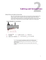
Page 21: ...s ports on the control surface as the Comms Ports are used as power and comms to ancillary panels 2x Comms Ports Network Port to Mainframe 2x USB Connectors 2x External PSU Connectors Monitor Out 1 2 3 4 5 4x Comms Ports 6 1 2 3 4 5 Kula AV K5P 1M E 19 Control Surface Note The Comms Ports provide power and comms to ancillary panels Comms ports not Ethernet ports DO NOT connect any Comms Ports to a...

Page 22: ...Surface Connectors Connector Description 1 2x PSU Connectors Kycon KPPX 4Pin or Compatible 12V DC 8 33A 2 2x USB 2 Connectors 3 Monitor MON Output to touch screen GUI 4 10 100 1000 base T RJ45 network connectors to the switcher mainframe 5 2x Comms Connection Important Note NOT Ethernet connections must be direct to a control surface Do Not use network switches or hubs CAT5 or above cables crossov...

Page 23: ...nches Touch screen monitor once the external monitor is connected to the Kula AV control surface a USB control lead shown above is connected allowing the touch screen functions to be used Information sticker from the side of the Control surface MON monitor output port KPP or KPX Note the K5P control surface is connected in exactly the same way MON monitor output port USB port When using a touch sc...

Page 24: ...or once the external monitor is connected to the Kula AV control surface a USB mouse can be used to control the Kula AV menus on the monitor screen Current Compatible Touch Screen Monitors iiyama T2250 MTS iiyama T2236 MSC B1 and B2 iiyama T2252 MTS GeChic On Lap 1502 ELO_1002L_1502L ...

Page 25: ...MAV AUD FADER Note Notice that there is an Input and Output socket Use the input socket only The loop through cannot be used Connect the Ethernet cable to the Comms port on the control surface Connect the Ethernet cable to the Input port MAV AUD FADER under side MAV AUD FADER Kula AV Control Surface Supplied Ethernet Cable Sticker on underside of the MAV AUD FADER ...

Page 26: ...Mainframe Layout and Connections Mainframe Layout and Connections Mainframe Overview The Kula AV mainframe has 1 card that has all the Mix Effects and Input Output video processing Kula AV Mainframe Front Card Location Main Card ...

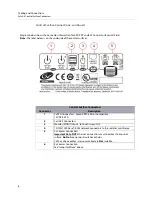
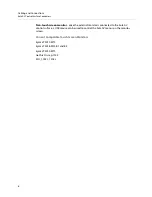
Page 27: ...ut Bi directional BNCs 4x SDI SDO BNC Inputs plus 2x Bi Directional Input Outputs Numbered 37 to 42 C GPIO 2x 25 Way D type GPIO connectors 1 22 23 44 D AES Input Output 1x 25 Way D type GPIO connectors E Reference 1x Ref In and 1x Ref out F Network 3x 10 100 1000 base T G USB 2x USB3 for external memory device or hard drives USB outputs are 5 V DC 0 9 A each H Serial 2X RJ45 RS422 Ethernet ports ...

Page 28: ... are 12x SDO Outputs at the rear of the Kula AV mainframe Input and Bi directional Input Output BNCs The diagram below displays are bi directional BNCs used as Inputs or Outputs Note The following pages that describe connectors on a Kula AV Mainframe unless indicated otherwise Bi directional Input Outputs Inputs 37 to 40 As Outputs 13 and 14 As Inputs 41 and 42 ...

Page 29: ...to each connector the LED s have different functions depending on the type communication they are receiving the list below describes the functions Connectors with XLR shells can be used to connect with these network connectors In each case LED Lit link Flashing traffic Left LED Right LED 1G bit 1000 base T GREEN GREEN 100Mbit 100baseT OFFGREEN 10Mbit 10baseT YELLOWGREEN No link OFF OFF Reference A...

Page 30: ...PO 6 4 GPO 28 5 GPO 8 5 GPO 30 6 GND 6 GND 7 GPO 11 7 GPO 33 8 GPO13 8 GPO 35 9 GPO 15 9 GPO 37 10 GPO17 10 GPO 39 11 GND 11 GND 12 GPO 20 12 GPO 42 13 GPO 22 13 GPO 44 14 GPO 1 14 GPO 23 15 GPO 3 15 GPO 25 16 GPO 5 16 GPO 27 17 GPO 7 17 GPO 29 18 GPO 9 18 GPO 31 19 GPO 10 19 GPO 32 20 GPO 12 20 GPO 34 21 GPO 14 21 GPO 36 22 GPO 16 22 GPO 38 23 GPO 18 23 GPO 40 24 GPO 19 24 GPO 41 25 GPO 21 25 GPO...

Page 31: ... 1 Pin 14 Pin 25 Pin 13 AES Pin outs AES Inputs Outputs Pin Signal 1 Out 7 8 2 GND 3 Out 5 6 4 Out 3 4 5 GND 6 Out 1 2 7 In 7 8 8 GND 9 In 5 6 10 In 3 4 11 GND 12 In 1 2 13 NC 14 Out 7 8 15 Out 5 6 16 GND 17 Out 3 4 18 Out 1 2 19 GND 20 In 7 8 21 In 5 6 22 GND 23 In 3 4 24 In 1 2 25 GND ...

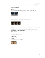
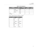
Page 32: ...er settings makes Kula AV able to control external equipment and a Slave setting lets Kula AV be controlled by external equipment RS422 1 3 Pin Configuration RJ45 Pin Color typical Function master mode 9 pin D Type SP1 9 pin D Type SP3 1 Orange White Tx1B 3 2 Orange Tx1A 8 3 Green White Tx3B 3 4 Blue Tx3A 8 5 Blue White RX3A 2 6 Green RX3B 7 7 Brown White Rx1A 2 8 Brown Rx1B 7 Cable screen GND GND...

Page 33: ...own White Rx2A 2 8 Brown Rx2B 7 Cable screen GND GND 9 9 Pin Master Slave 1 Ground Ground 2 Rx A Tx A 3 Tx B Rx B 4 Tx Common Rx Common 5 Spare Spare 6 Rx Common Tx Common 7 Rx B Tx B 8 Tx A Rx A 9 Ground Ground RS422 2 4 Pin Configuration RJ45 Pin Color typical Function master mode 9 pin D SP2 9 pin D SP4 ...

Page 34: ...18 Cabling and Connections Mainframe Connections ...

Page 35: ...rack environments Attention should be paid to the cooling information for the mainframe The ambient temperature for all the supplied equipment should not exceed the limits of 5 and 40 C 41 to 104 F at a relative humidity of 10 to 90 non condensing Installing the equipment in a clean environment with moderate temperature and humidity will promote a long and trouble free equipment life ...

Page 36: ... into a desk using appropriate Pan Head M4 screws with a Max head diameter of 8 8mm 0 34 Inches At each end of each Control Surface there are two 4 5 mm 0 18 Inches fixing point holes for the screws Note The Kula AV control surface should preferably be mounted in a desk which is open underneath Note If the desk is not open underneath enough room has to be left underneath for ventilation and for ro...

Page 37: ...to lock it into position The frame Ears have small round magnets that locate into two round depressions at each end of the MAVRow frame Carefully place the Ears into position being careful not to trap your fingers Pins on the MAV module fit into the holes and then slot to the right Pins Holes Place the MAV AUD FADER into the frame and locate the pins into the holes in the frame Then slide to the r...

Page 38: ...is ESSENTIAL 2 Air intakes situated at the front and on both sides are to allow the inlet of cooling air and MUST NOT BE OBSTRUCTED Cooling Fan Failure IF THE COOLING FANS ONTHE SWITCHER MAINFRAME SHOULD STOP FOR ANY REASON THEN THE SYSTEM SHOULD BE SWITCHED OFF IMMEDIATELY OR PERMANENT DAMAGE MAY RESULT Depending on the length of time the mainframe has been run with no fan the unit may need to be...

Page 39: ...on Manual Warning Note Do not obstruct air intakes to fans and air vents on any piece of equipment listed in this manual Please pay particular attention to the air intakes at sides and the vents at the rear of the Mainframe ...

Page 40: ...me front door will have to be opened To do this unscrew the door locking screws on either side of the door then pull outwards and lower as shown in the diagram below 5 The mainframe is fastened to the rack system using 4x M6 1 4 inch screws screws are available from rack suppliers Note The Kula AV Mainframe is heavy 14kg 30 3lb and will require two people to lift into position using correct liftin...

Page 41: ... a joining plate Desk Mount The rack mount ear mounting brackets can be set to two different positions horizontal with the mounting holes facing upwards and vertically for Rack Mount as described in the 19 Rack Mount description this will allow the unit to be secured to the underside of a desk With the rack mount ears in the horizontal position the unit can be secured to a desk using 4x screws Mou...

Page 42: ... to the rack sides 19 Rack Mount using two Mav Remote units with a Joining Plate Two Mav Remote units can be joined together using a joining plate which allows the units to span across the full width of the rack and fasten to the rack without the support of a rack tray Note The Mav Remote must have ventilation to allow cooling and must not be installed into an enclosed space The unit is secured to...

Page 43: ... 19 rack is exactly the same for both Aux panels The ears of the Aux Panels have 2x holes on each side use the correct rack mount screws and fixings in the 4x mounting holes to secure the Aux panel to the rack as shown below Make sure that enough access is allowed behind the Aux panel to connect the external PSU and network cable ...

Page 44: ...28 Environment and Location Ancillary Panels ...

Page 45: ... AC Power Cables are plugged into the IEC connectors and turned On at the AC mains supply Checking the Kula AV Power Supplies Kula AV mainframe power supplies are hot swappable Replacing power supplies should only be attempted by qualified personnel To see that the power supplies are working correctly when mains power is applied a green power LED is lit as shown below With the power supplies un pl...

Page 46: ...ther is for redundancy Caution The Power Supplies have NO user serviceable parts inside and are welded shut Do not attempt to open the power supply cases The power supply connector plug that connects to the control surface is a 4 pin Snap and Lock type care should be taken when connecting and un connecting Note Make sure that the mains power is turned Off before connecting the PSU to the control s...

Page 47: ...E 19 Control Surface Kula AV K5P 1M E Control Surface Width Depth Height 482 6 mm 19 Inches 221 5mm 8 72 Inches 87 9mm 3 46 Inches 146 5 mm 5 79 Inches total height including T Bar Weight Approx 3 6Kg 7 14lb Environmental 41 to 104 F 5 to 40 C non condensing ...

Page 48: ...32 Dimensions Control Surface Dimensions Desk Cutout Dimensions for K5P 1M E 19 Control Surface ...

Page 49: ...tion Manual Mainframe Dimensions Kula AV Mainframe Kula AV Mainframe Width Depth Height 482 6 mm 19 Inches 604 8mm 23 81 Inches 87mm 3 42 Inches Weight Approx 14Kg 30 3lb Environmental 41 to 104 F 5 to 40 C non condensing ...

Page 50: ...34 Dimensions MAVRow MAVRow Diagram shows the end view of the MAVRow MAVRow Depth Height 140 mm 5 51 Inches 70 4 mm 2 77 Inches surface of MAV GUI to the bottom of the body Weight Approx TBC ...

Page 51: ...MAV AUD FADER MAV AUD FADER Width Depth Height 160 mm 6 29 Inches 140 mm 5 51 Inches 58 9 mm 2 31 Inches surface of MAV AUD FADER to the bottom of the body Weight Approx 900g 31 74oz Environmental 41 to 104 F 5 to 40 C non condensing ...

Page 52: ...s Ancillary Panels Mav Remote Dimensions Mav Remote Dimensions Width Depth Height 9 44 inches 239 9 mm 12 95 inches 329 mm 2 00 inches 50 7 mm including feet Weight 4 29 lbs 1 95kg Environmental 41 to 104 F 5 to 40 C non condensing ...

Page 53: ...Aux Panel Dimensions Width Depth Height 19 inches 482 6mm 1 51 inches 38 4mm 1 72 inches 43 6 mm Weight 2 2 lbs 1kg Environmental 41 to 104 F 5 to 40 C non condensing Note The diagram above displays the LCD Aux Panel dimensions The LED Aux Panel has exactly the same dimensions ...

Page 54: ...38 Dimensions Ancillary Panels ...

Page 55: ...onnectors for Comms and 12V 0 42A power supply NOT Ethernet connections Do Not use network switches or hubs CAT5 or above cables crossover cables are Not suitable External Power Supplies Power Supply Description External PSU for the KPP Control Surface 2x Fully independent external PSU modules with separate mains power feeds via 2x 10A IEC leads Output from each PSU 12V DC 100W via Kycon KPPX 4 Pi...

Page 56: ...i 59 94Hz ANSI SMPTE 260M 292M B 1080p 30Hz sF ANSI SMPTE 274M 12 as per RP211 1080p 29 97Hz sF ANSI SMPTE 274M 13 as per RP211 1080p 25Hz sF ANSI SMPTE 274M 14 as per RP211 1080p 24Hz sF ANSI SMPTE 274M 15 as per RP211 1080p 23 976Hz sF ANSI SMPTE 274M 16 as per RP211 1080p 30Hz ANSI SMPTE 274M 7 292M G 1080p 29 97Hz ANSI SMPTE 274M 8 292M H 1080p 25Hz ANSI SMPTE 274M 9 292M I 1080p 24Hz ANSI SMP...

Page 57: ...ync according to system standard Output Impedance 75 ohms Mainframe Inputs Inputs 40x Tri standard SD SDI HD SDI 3Gbps SDI each on 1x BNC Mainframe Inputs Formats Levels SDI Input Format Tri Standard 1080p 2 97Gbps HD 1 485 Gbits second and SD 270Mbits second serial digital interface as per ANSI SMPTE 259 292M Analogue HD Reference 300mV tri level sync 6dB Analogue SD Reference 300mV sync with opt...

Page 58: ... direct to MAV modules Do Not use network switches or hubs CAT5 or above cables crossover cables are Not suitable Mav Remote Power Supplies Power Supply Description To the Mav Remote 2x Fully independent external PSU modules with separate mains power feeds via 2x 10A IEC leads Output from each PSU 12V DC 100W via Kycon KPPX 4 Pin or Compatible connectors to the Mav Remote 2 supplied as standard pe...

Page 59: ...in a local phone number for the support center nearest you please consult the Contact Us section of Grass Valley s website www grassvalley com An online form for e mail contact is also available from the website Corporate Head Office Grass Valley 3499 Douglas B Floreani St Laurent Quebec H4S 2C6 Canada Telephone 1 514 333 1772 Fax 1 514 333 9828 www grassvalley com ...

Reviews: