AIRBLADE® DRYER
Mix and Match
74
Belanger, Inc. * 1001 Doheny Ct. * Northville, MI 48167 * Ph (810) 349-7010 * Fax (810) 380-9681
1MANUL011
Installation
10-Nozzle Frame Assembly: Floor Mounted
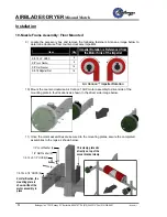
9) Locate the accessory box and remove the following fasteners. Also see image below to
determine clockwise from counter-clockwise impellers
Item
Qty
Impeller Rotation is Referenced from
the Motor Side of the Impeller
3/8-16 x 2” HHCS
8
3/8”
Lock Washer
8
3/8”
Flat Washer
16
3/8-16 Regular Nut
16
Air Cannon™ Impeller Rotation
10) Mount the counter-clockwise Air Cannon 10HP motor assembly to driver side of the
mounting plate in four locations as shown in the driver side image below.
11) Once the motor assemblies are secured to the mounting plates, secure the completed
assemblies to the legs as shown below.
1/2” Lock Washer (4)
1/2” Flat Washer (4)
1/2-13 x 3-1/2” HHCS (2)
1/2-13 x 4-1/2” HHCS (2)
For clarification, the
mounting plate is
shown without the
motor assembly in
place
This clamp plate sits
directly on top of the
corner bracket clamp


