


belfuse.com/power-solutions
USER MANUAL
10
Without using the battery sense connection as shown in Figure 9 the AC voltage drop is measured across the battery connection terminals
on the LDX-U20. The measured resistance will be in this case:
Rmeasured=Ri+Rcables. When high Ah batteries and / or small and long cables are used Rcables can be > Ri. Anyhow a connection problem
as for example a loose contact can be detected by this measurement method.
By using the battery sense connection (a “Kelvin” type connection) as shown in Figure 10 the AC voltage drop is measured directly at the
battery terminal. In this case the measured resistance is exactly the battery internal resistance Ri, independently on the cables length and
size.
It is recommended to use this method to have an accurate reading of the battery internal resistance and thus an accurate prediction of the
battery health status.
If the battery sense cables length is > 2m it is recommended to twist the 2 wires together in order to increase the noise immunity.
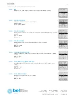
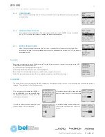
3.6 BATTERY CHARGER
The battery charger supports various chemistries such Lead-Acid, Nickel, Lithium and every other battery chemistry assuming that the
charging voltage and charging current values are provided by the battery manufacturer. The charging algorithm is shown on Figure 8. Other
charging algorithms can be implemented by request.
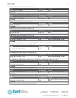
The user must set to the unit the following parameters to allow the charger to perform correctly:
• Battery chemistry: selectable between Lead-Acid, Nickel, Lithium (see §5.2.2).
• Battery nominal voltage: between 12V and 28V (see §5.2.3).
• Battery capacity: between 1.2Ah and 150Ah (see §5.2.4).
• Battery charging voltage: provided by the battery manufacturer (see §5.2.5).
• Battery charging current: provided by the battery manufacturer (see §5.2.6).
• Battery deep discharge voltage (see §5.2.7).
The battery charger automatically reduces the current to avoid exceeding the maximum input current (20A) in case of high current load. For
example if the load is consuming 19A and the charger current is set to 3A, the charger current is automatically reduced to 1A to avoid the
20A input current limit.
The charger voltage is independent on the input voltage (power supply), and is user settable.
Figure 8. Battery charging algorithm
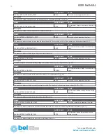
The battery charge terminates in case at least one of the following conditions are satisfied:
•
Low current:
The measured battery current is lower than 10% of the “Battery charge current”.
•
Timer:
the charge is terminated after the battery has been charged for a predetermined amount of time. The value is automatically
calculated by the device.
For Nickel batteries only the following conditions are also checked:
•
Temperature Cutoff (TCO):
The battery temperature if higher than the “Battery maximal temperature” (§5.2.11) minus 3°C for more than one
minute. For example if the maximal battery temperature is set to 60°C, the charge terminates in case the temperature is higher than 57°C.


