


19
8.4 Lineariser
Both indicators can be supplied with a sixteen
point lineariser that may be adjusted to
compensate for almost any non linear variable. For
example, a level signal from a horizontal cylindrical
tank may be linearised by the indicator to display
the tank contents in linear volumetric units.
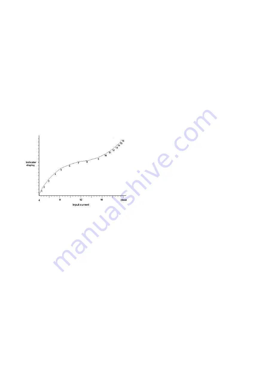
Fig 13 shows a typical linearising characteristic. Up
to sixteen break-points may be programmed to
occur at any input current between 4 and 20mA.
The slope between adjacent break-points may be
set anywhere between -1250 and +1250 display
counts per milliamp. Greater slopes may be
programmed, but the indicator performance will be
degraded. A linear characteristic can be obtained
by programming just two points, one at 4mA and
the other at 20mA.
Fig 13 Typical indicator characteristic
The lineariser software does not change the main
programme menu, but the CAL and SEt functions
are extended as shown in Fig 14. As with a linear
indicator, calibration may be performed with an
external calibrator using the 'CAL' function, or from
the internal references using the 'Set' function.
8.4.1
Calibration using an external current
source
This method allows direct calibration with a current
source, and is preferred when traceability is
required. If the exact system non-linearity is
unknown, the method also allows direct calibration
from the variable to be displayed. e.g. the output
from a level sensor in an irregular tank may be
displayed in linear volumetric units by filling the
tank with known incremental volumes and
calibrating the indicator to display the sum of the
increments at each break-point.
The number of break-points required should first
be entered using the Add and dEL functions. In
both these functions the indicator initially displays
the current break-point and the total number of
break-points being used. e.g.
5
13
current
total number of
break-point
break-points
'Add'
Add a break-point
Adds a new break-point before the
displayed break-point. The calibration of
existing break-points is not changed, but
the identification number of all subsequent
break-points is increased by one.
'dEL'
'Remove a break-point
Removes the displayed break-point and
joins the preceding break-point to the
following break-point with a straight line.
The identification number of all subsequent
break-points is decreased by one.
To add a break-point select 'CAL' from the main
menu and press
P
to enter the 'Add' function; press
P
again to reveal the current and total number of
break-points. Each subsequent operation of the
P
push-button will introduce an additional break-
point. When adding a break-point to a calibrated
indicator, the insertion position can be selected
using the
Up
and
Down
push-buttons.
The delete break-point function 'dEL' operates in a
similar manner to the 'Add' function described
above.
When the required number of break-points has
been entered, return to the sub-menu by pressing
E
. The indicator will display 'Add' or 'dEL'
depending upon the last function used. Each
break-point can now be programmed
Select 'PtS' from the sub-menu and press
P
which
will select the first break-point '0 n', where n is the
total number of break-points entered. The selected
break-point can be changed using the
Up
and
Down
buttons. When the required break-point has
been selected press
P
. Set the indicator input
current to the exact value at which the break-point
is to occur, and adjust the indicator display using
the
Up
and
Down
buttons and
P
to move between
digits. When the required display has been set,
press
E
to enter the information and return to the
sub-menu from which another break-point can be
selected.
Summary of Contents for BA527C
Page 1: ...Issue 3 5th March 2009 BA527C BA528C loop powered 4 digit panel mounting indicators Issue 3...
Page 8: ...8...
Page 18: ...18 Fig 12 Alarm programme menu...
Page 21: ...21...


